2 — INSTALLATION AND WIRING
pg. 5
Return to TOC Curtis AC F2-A, F4-A, F6-A Motor Controllers – FOS 4.5 – April 2022
2 — INSTALLATION AND WIRING
PHYSICALLY MOUNTING THE CONTROLLER
Use the controller's outline and mounting-hole dimensions to determine the optimum mounting
location. Properly installed, the controller meets the IP65 requirements for environmental protection
against dust and water. Nevertheless, in order to prevent external corrosion and leakage paths from
developing, choose a mounting location to keep the controller as clean and dry as possible. Protect
all ends of the low-power (signal) harness from excessive moisture and water (e.g., any toggle switch,
sensor, and device connections on the vehicle).
Do not pressure wash the controller or its connectors and terminals.
Mount the controller to a at surface devoid of protrusions, ridges, or a curvature that can cause damage
or distortion to its heatsink (base plate). Secure the controller using evenly torqued bolts to the vehicle’s
mounting surface. Applying a thin layer of thermal joint compound improves heat conduction from
the controller heatsink to the vehicle’s mounting surface. Typically, when properly mounted to a larger
(smooth) metal surface, an additional heatsink or cooling fan is not necessary to meet the application’s
peak and continuous current ratings.
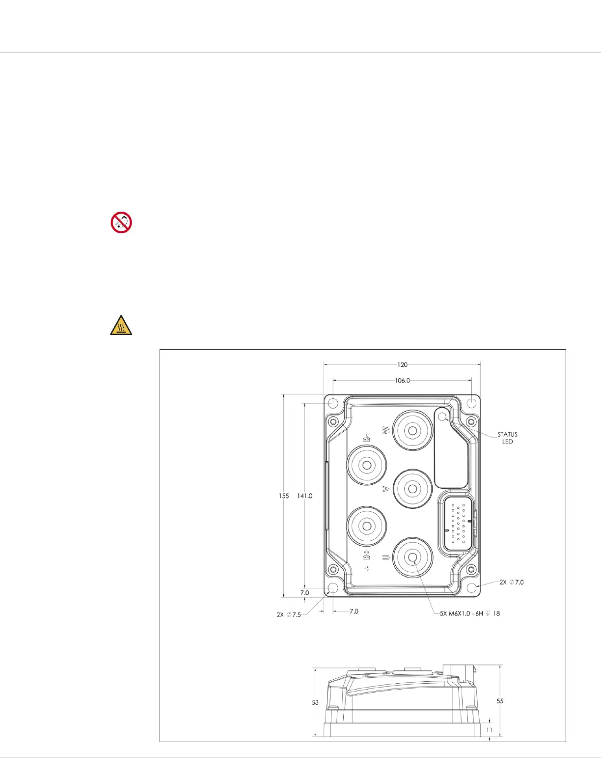
Apply a hot surface label to the controller compartment.
Figure 4
AC F2-A dimensions
Dimensions are in millimeters

 Loading...


