3 — APPLICATION-SPECIFIC FEATURES
pg. 33
Return to TOC Curtis AC F2-A, F4-A, F6-A Motor Controllers – FOS 4.5 – April 2022
VOLTAGE LIMITS
e F-Series controllers have both hardware and parameter-based voltage limits. During regenerative
braking, the system voltage increases as the motor acts like a generator to slow the vehicle. e
overvoltage protection cuts back the regenerative braking (regen) to prevent damage to the traction
battery and other electrical system components due to the increased voltage once it is above the
normal-voltage region. Regen cutback typically occurs when the traction-battery is near full charge,
rather than when it is near its discharged voltage. Conversely, as the traction-battery nears depletion,
strong acceleration or load demands can lower the battery voltage. To prevent the controller from
operating below its full capabilities, the undervoltage protection will reduce the drive current when
the voltage is below the normal-voltage region. Both of these protection methods help to prevent
vehicles and systems from operating at voltages above and below their design or the application’s
thresholds. Understanding the voltage limit regions will aid in setting the battery and speed controller
related parameters.
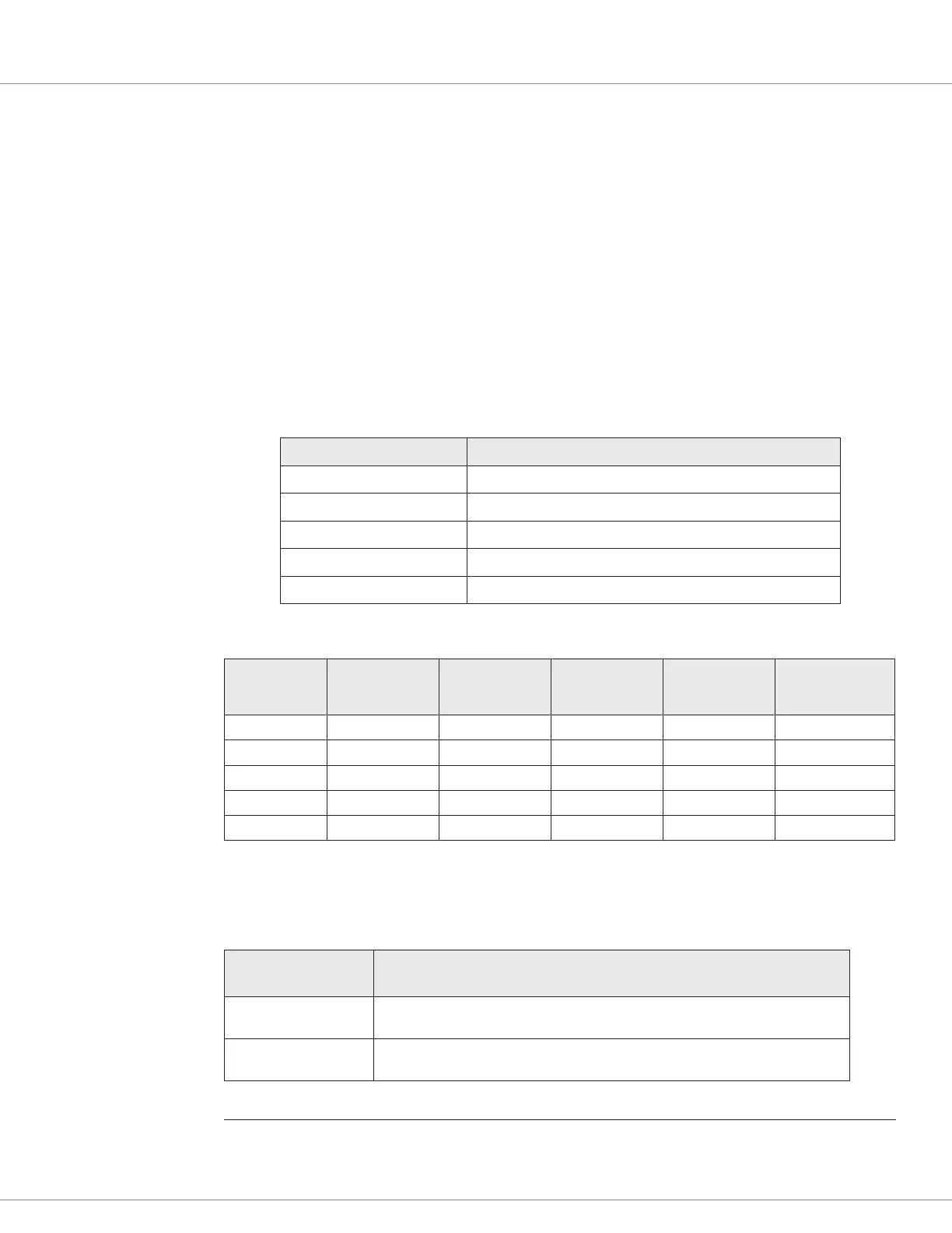
e following conditions dene the standard F-Series operating voltage ranges.
Condition Operating Voltages
Severe over-voltage 150% of maximum nominal rating
1
Over-Voltage 125% of maximum nominal rating
1
Under-voltage 50% of maximum nominal rating
Severe under-voltage 40% of maximum nominal rating
Brownout 33% of maximum nominal rating
e voltage ranges, based upon model voltage, are in the voltage table below
2
.
Nominal
Battery
Voltage
Brownout
Severe
Under-voltage
Under-voltage Over-voltage
Severe
Over-voltage
24V 8V 9.6V 12V 30V 36V
24-36V 8V 9.6V 12V 50V 54V
36-48V 12V 14.4V 18V 63V 72V
48-80V 16V 19.2V 24V 100V 120V
72-96V 24V 28.8V 36V 120V 130V
When the supply voltage is within the normal operation zone, the controllers operate with their full
current and features. To narrow the normal operating window, for example, to tailor an application
to work with a more restrictive battery, change the User Overvoltage and Undervoltage parameters.
Condition
User/Parameter Defined
(Application Setup/Battery Setup/…Under-and Overvoltage parameters)
Over-voltage Either the Maximum Voltage (voltage-range table, above), or
User_Overvoltage × Nominal _Voltage, whichever is lower.
Under-voltage Either the Minimum Voltage (voltage-range table, above) or
User_Undervoltage × Nominal_Voltage, whichever is higher.
1
There are slightly higher over-voltage limits for the 36V and 48V models than in this table’s definitions. See the above voltage table.
2
See Appendix E for the models and specifications. See the F-Series controller datasheets, available on the Curtis website,
for new model updates.

 Loading...


