7 — DIAGNOSTICS AND TROUBLESHOOTING
Curtis AC F2-A, F4-A, F6-A Motor Controllers – FOS 4.5 – April 2022 Return to TOC
pg. 198
7 — DIAGNOSTICS AND TROUBLESHOOTING
e Troubleshooting Chart, Table 24, describes the fault ash codes. e faults list is in the numerical
ash code order. e fault’s name, VCL name and CAN Object Index are listed, including the fault types.
Possible causes, the set and clear conditions and the fault actions are listed. Fault actions are “what the
controller will do” when the fault is active. Table 23 lists the fault actions and their associated 'bits' when
using the System_Action variable (0x4E00 0x00). Table 22 is a quick index to the faults by ash codes.
Faults, aer the set condition(s) have been resolved, are usually cleared by cycling the keyswitch (On-
O-On), yet can be handled using the applicable VCL Reset function, or the CAN NMT Reset function.
ese are collectively referred to as Reset Controller.
THE DIAGNOSTICS PROCESS
Obtain diagnostics information in either of three ways: (1) by observing the fault codes ashed by the
controller’s status indicator, (2) by reading the indicated fault ( ) in the Curtis Integrated Toolkit
TM
Programmer tool, or (3) the CAN Emergency Messages.
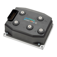
e status indicator is a translucent window on the cover, which blinks red and yellow LEDs. Its
illumination indicates the following information:
O: Controller is not powered on, or is severely damaged.
Slow yellow blinking: Controller is operating normally.
Solid yellow or orange: Controller is in ash program mode, or corrupted soware is
preventing the unit from completing the startup sequence (boot process).
Red/yellow ashing pattern: Fault code, review the fault table.
Solid red: Internal hardware fault detected by the supervisor or primary microprocessor, or
the controller has no soware loaded.
Fast ashing red: Non-production/experimental/custom device prole soware.
e Troubleshooting Chart Index, Table 22, indicates both the controller’s LED ash sequences and
the CANbus Emergency Message hexadecimal Error Code values. e fault ash pattern is decimal.
For example, the Driver 1 Fault is assigned the ash code 10-1, which illuminates in a sequence of
10 red LED ashes (x10) followed by 1 yellow LED ash (x1) before repeating. e hexadecimal
code is 0xA1, which will be the Error Code value in the CAN Emergency message, explained below.
When using the Curtis Integrated Toolkit
TM
Programmer tool to diagnose faults, the active faults are at
the top of the menu panel. If a fault has more than one possible cause, it indicates the “type” number.
Within the System Monitor menu, the Fault History menu provides additional information; Count
indicates the number of occurrences since the Clear History was performed. e menu item Time
indicates the KSI hours, provided in seconds (#sec/3600 = hours) when the present fault occurred,
while the menu’s First Time item keeps track of the fault’s rst occurrence, should multiple faults
follow before the history is cleared. e Type, as listed at the top of the menu panel, is repeated and
is the current “fault type” for faults having more than one type. Figure 42 is an example of the CIT
Programmer’s fault-diagnosis usage. e illustrated sequence, panels le to right, are for the two
types of the Main Contactor Did Not Close fault, which are also illustrated in the CAN Emergency
Messages – Active Faults section, as examples (2a) and (2b) below.
1
Panel 1: An Active Fault with Type 1. First occurrence (Count = 1) with Time and First
Time are equal. e active fault Type matches.
2
Panel 2: Second occurrence of the same fault Type as in panel 1. Note the Time dierences,
with First Time matching between panels 1 and 2.

 Loading...


