2 — INSTALLATION AND WIRING
pg. 25
Return to TOC Curtis AC F2-A, F4-A, F6-A Motor Controllers – FOS 4.5 – April 2022
Drivers 6 and 7 are lower-current digital (On/O) drivers. Use the drivers for dashboard LEDs,
piezo-electric buzzers and other low-current switched loads (i.e., high input impedance devices able
to accept full coil supply voltage).
e controllers have two special purpose drivers.
• Driver 1 supports proportional valves, oering a higher frequency and ner current accuracy
in addition to the typical dither-related parameters. e proportional driver’s minimum duty
cycle is 11%, because the current regulation is unavailable below this percentage.
• Driver 2 supports a 3A load for EM Brake usage.
Table 11 summarizes the drivers. Drivers 2–5 also support dither and current control, albeit at an
accuracy of 15%. e parameter Driver_Output_Frequency collectively sets the PWM frequency for
Drivers 2–5, whereas Driver 1 is xed. To implement additional driver controls, use VCL. As noted
in Table 8, these drivers are congurable as switch inputs, and are included in that group as well.
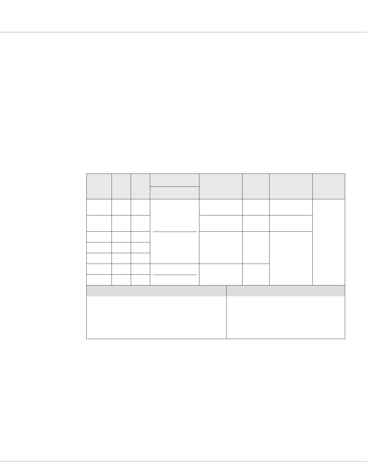
Table 11 Driver Outputs Electrical Specifications
Input
Signal
Name
23-Pin 35-Pin
Switching Side
PWM (Duty Cycle)
Frequency
Output
Current
2
Current
Measurements
3
Input
Impedance
Driver 1 7 2
Low-Side (only)
0-100% selectable
6
18 kHz
(xed, ± 500 Hz)
2 Amps 40 mA – 2.6A
4
> 30k Ω
Driver 2 4 5
200 – 2000 Hz
1
(adjustable)
3 Amps 450 mA – 3.9A
4
Driver 3 5 4
200 – 2000 Hz
1
(adjustable)
2 Amps
40 mA – 2.6A
4
Driver 4 6 3
Driver 5 3 6
Driver 6 n/a 19
Low-Side (only)
5
0 or 100% (On/Off)
N/A
(no PWM)
1 Amp
Driver 7 n/a 20
VCL Functions VCL Monitor Variables
Automate_Driver( )
Put_Driver( )
Battery_Compensate( )
—
Driver_Output_Frequency
Driver_Output_Frequency
Driver_Pwm
Driver_Voltage
Driver_Pwm_Pull_In_And_Hold
Driver_Voltage_Pull_In_And_Hold
Driver_Current
1
The PWM Frequency parameter collectively sets Drivers 2–5 frequency (± 10%).
2
The sum of all driver currents shall not exceed Coil Supply (pin 13) current rating.
3
2–130% of continuous rating. Minimum duty-cycle of 10% required for current measurement.
4
Over-current shut down occurs at 120% of current rating in < 8 ms | 200% < 1 ms.
5
Output Low Voltage: < 0.25V at full current and 100% PWM.
6
Proportional Driver 1, the minimum current regulation is 11% duty cycle (operate > 11% duty cycle).
Coil impedance affects the lower limit of current control, where I = (11% PWM x Bat Voltage)/Coil Impedance (i.e., simplified
steady state conditions, as the basic starting point of the proportional drivers current regulation limit).

 Loading...


