2 — INSTALLATION AND WIRING
pg. 29
Return to TOC Curtis AC F2-A, F4-A, F6-A Motor Controllers – FOS 4.5 – April 2022
In all cases, connect the sensor to the controller’s I/O ground. is is the signals’ reference.
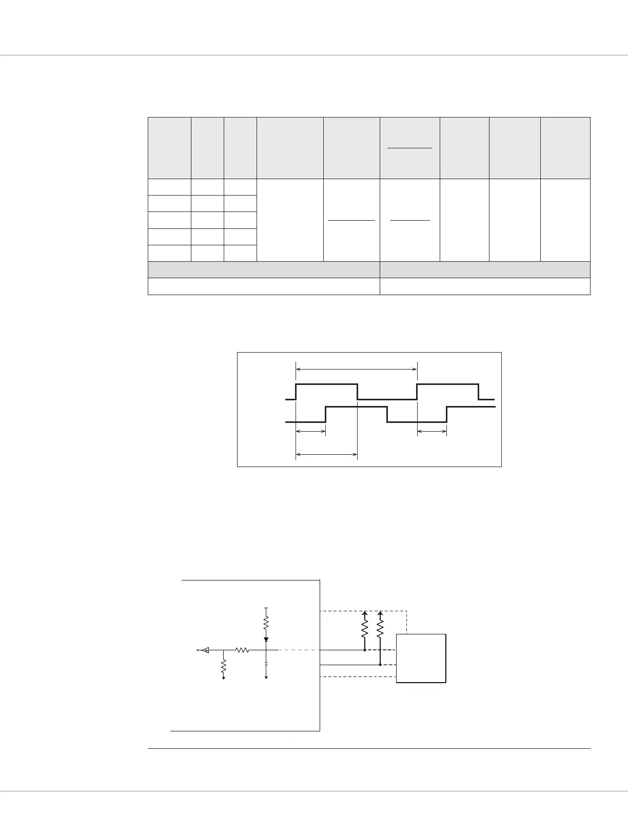
Table 15 Digital/Quadrature Encoder Electrical Specifications
Signal
Name
23-Pin 35-Pin
Input Voltage
range
High/Low
Voltage
Threshold
Pull-up
Resistance
Input
Impedance
Maximum
Frequency
A-B Phase
Range
Phase Duty
Cycle
Enc 1A 17 31
0 – 15V
4V max
Rising-edge
1V min
Falling-edge
2k Ω to 5k
5k Ω
250k Hz
2
90° ± 30°
50 % ±
10 %
Enc 1B 18 32
Enc 1C
1
19 11
Enc 2A n/a 12
Enc 2B n/a 14
VCL Functions VCL Monitor Variables
Motor_RPM
The application must maintain these illustrated signal tolerances throughout the application’s
operating conditions, including voltage, temperature, speed and torque ranges. ACIM applications
use the quadrature encoder.
Channel A
Channel B
360
°
electrical (1 cycle)
>10 μs90
°
±30
°
180
°
±18
°
F-Series controllers using FOS versions 4.0 and higher are able to support encoder input frequencies
up to 250 kHz. Encoders operating above 30 kHz, must use an external pull-up resistor circuit as
illustrated. Use the controller’s external supplies (5V or 12V) as a source for the pull-up resistors, while
observing the external supply’s current limits. Follow the encoder manufacturer recommendations
when sizing the resistors, but typical values are 220Ω for 5V and 470Ω for 12V.
Input 3 / Enc 1A
Input 4 / Enc 1B
Encoder_A
Encoder_B
External Pull-up Circuit
Use +5 or +12 Volts
OPEN-COLLECTOR
ENCODER
---------------
> 30 kHz
F-SERIES CONTROLLER
ENCODER INPUT CIRCUIT
+5V
2kΩ
1nF
R1
R2
The typical input circuit for the quadrature encoders.
The values of R1/R2 vary between controller models.
The 5V/2kΩ pull-up is enabled when the Quadrature encoder
is selected for input type (Position Sensor Type = Quadrature).
The external pull-up circuit is required for Quatrature Encoders with input frequencies greater than 30 kHz.
* Follow the encoder manufacturer recommendations when sizing the resistors, but typical values
will be 220Ω for 5V and 470Ω for 12V. When using the controller’s +5 or +12 volt external power
supplies for other devices, ensure the devices always operate within the supply’s current limit.
Ground
Power Supply
+5 or +12V
Ext Supply
I/O Gnd
uP
R*
R*
1
Specialty Input (future).
2
Encoders >30kHz require an external pull-up (see circuit).

 Loading...


