2 — INSTALLATION AND WIRING
pg. 31
Return to TOC Curtis AC F2-A, F4-A, F6-A Motor Controllers – FOS 4.5 – April 2022
0
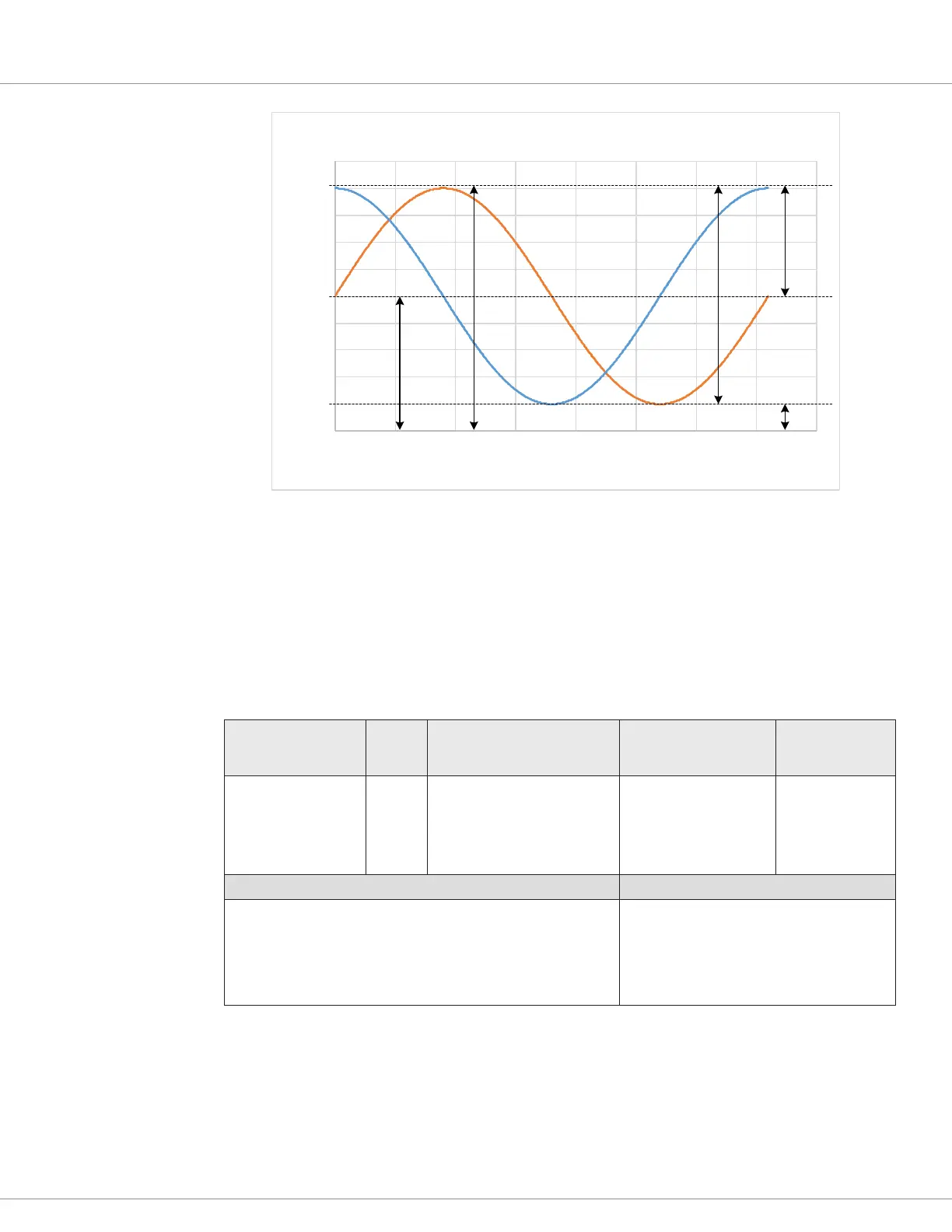
0.5
1
1.5
2
2.5
3
3.5
4
4.5
5
0 50 100 150 200 250 300 350 400
)V( tuptuO
Electrical Degree
Definitions
V
PP
V
Amp
Sin/Cos Max
Sin/Cos Min
V
off
Motor Temperature Input
e traction motor’s temperature sensor input measures the resistance of the connected sensor. e
controller supports KTY8x, and PT1000 temperature sensors. A parameter-VCL sensor conguration
prole allows the usage of custom solutions, with a maximum source current of less than 2 mA. e
controller is unable to use low resistance sensors, such as the PT100.
In all cases, connect the sensor’s ground/negative lead to the controller’s I/O ground.
Table 17 Motor Temperature Sensor Specifications
Signal Pin
Temperature
• Type
4
Resistance
Measurement Range
Accuracy
Motor Temp 8
–40 – 250°C
1
• KTY83-122
2
• KTY84-130
2
• KTY84-150
2
• PT1000
3
250 – 5k Ω ± 20 Ω @ ≤ 2k Ω
VCL Functions VCL Monitor Variables
Motor_Temperature
MotorTempCutback
Analog_Input_Volts_2
MotorTemp_Sensor1_Resistance
MotorTemp_Sensor2_Resistance
1
LOS Mode: 100°C in case of sensor failure.
80°C in case of disabled sensor.
2
±5°C full range temperature accuracy.
3
±15°C for 24V F2-A, ±5°C for other models.
4
When using custom sensors, note that maximum resistance measurement range supported in default configuration is 4k Ohms.
Temperature sense accuracy does not apply to custom sensors.
Custom sensor setup is via VCL. Consult Curtis.

 Loading...


