EasyManua.ls Logo

Kohler Curtis F Series User Manual

Kohler Curtis F Series
277 pages
To Next Page IconTo Next Page
To Previous Page IconTo Previous Page
Page #215 background imageLoading...
Page #215 background image
7 — DIAGNOSTICS AND TROUBLESHOOTING
pg. 207
Return to TOC Curtis AC F2-A, F4-A, F6-A Motor Controllers – FOS 4.5 – April 2022
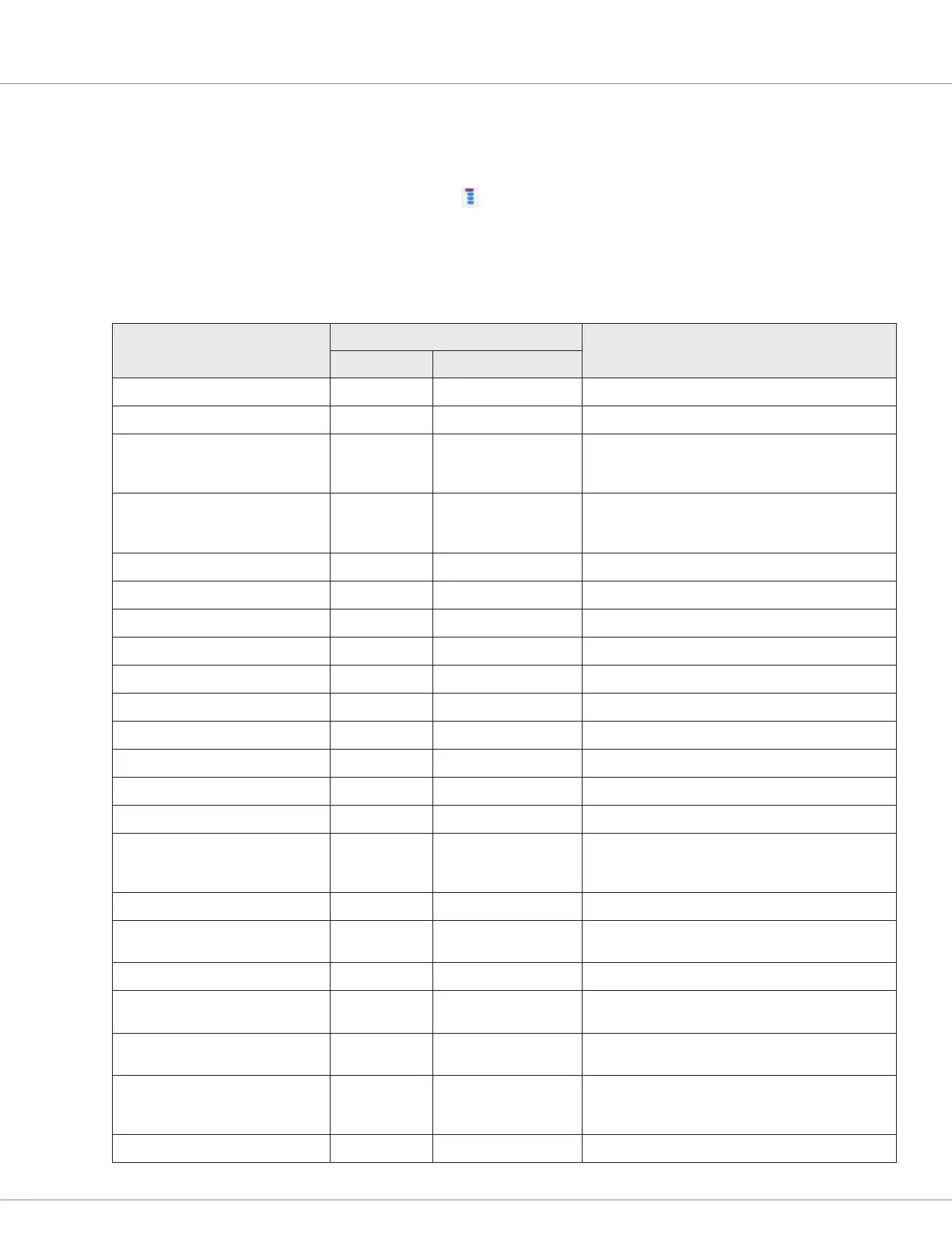
FAULT ACTIONS
e fault actions (eect of fault) in Table 23 use the action code bits individually or when combined as
listed in the fault action column in Table 24. e variable System_Action (0x4E00), which is available
in the CIT Programmer List View ( ), or TACT, returns the decimal number corresponding to the
active fault action bit(s). e example illustrates how to determine and plan for faults in both single
and dual motor applications.
Table 23 Fault Actions
Fault Action
1
Action Code
Description
Hex Bit(s)
NO_ACTION 0x00000000
ShutdownMotor 0x00000001 1 Disables the motor.
ShutdownMainContactor 0x00000002 2
Shut down the Main contactor.
Opens the main by de-energizing the main
contactor driver, only if Main Enable = On.
ShutdownEMBrake 0x00000004 3
Shut down the EM Brake.
Sets the EM Brake by de-energizing the driver, only
if the parameter Set EM Brake On Fault = On.
ShutdownThrottle 0x00000008 4 Set the Throttle_Command = 0%.
ShutdownInterlock 0x00000010 5 Set the Interlock_State = Off.
ShutdownDriver1 0x00000020 6 Shut Down Driver1 (e.g., turn off the driver’s PWM).
ShutdownDriver2 0x00000040 7 Shut Down Driver2 (e.g., turn off the driver’s PWM).
ShutdownDriver3 0x00000080 8 Shut Down Driver3 (e.g., turn off the driver’s PWM).
ShutdownDriver4 0x00000100 9 Shut Down Driver4 (e.g., turn off the driver’s PWM).
ShutdownPD 0x00000200 10 Shut down Proportional Driver (legacy name).
FullBrake 0x00000400 11 Set the Brake_Command = 100%.
ShutdownPump 0x00000800 12 Disables the pump.
TrimDisable 0x00001000 13 Disable Dual Drive trim calculation.
SevereDual 0x00002000 14
For a Dual Drive system, one controller has a severe
fault but the main contactor must stay closed so the
other controller can continue to operate.
ShutdownSteer 0x00004000 15 Steer angle = 0° (Dual Drive applicable).
LOSDual 0x00008000 16
For a Dual Drive system, it uses the max speed set
by the Dual_LOS_Max_Speed parameter.
ShutdownDriver5 0x00010000 17 Shut Down Driver 5 (e.g., turn off the driver’s PWM).
ShutdownDriver6 0x00020000 18
Shut Down Driver 6 (as applicable to the controller;
e.g., turn off the driver’s PWM).
ShutdownDriver7 0x00040000 19
Shut Down Driver 7 (as applicable to the controller;
e.g., turn off the driver’s PWM).
ShutdownCoilSupply 0x00080000 20
Shuts down (turns off) the Coil Supply (return)
voltage. (Note, based upon the controller model, this
will also shut down the low-side drivers).
ShutdownVehicle 0x01000C0F 25, 12, 11, 4, 3, 2, 1 Evokes all Fault Actions as per the indicated bits.

Table of Contents

Question and Answer IconNeed help?

Do you have a question about the Kohler Curtis F Series and is the answer not in the manual?

Kohler Curtis F Series Specifications

General IconGeneral
BrandKohler
ModelCurtis F Series
CategoryController
LanguageEnglish

Summary

1 — OVERVIEW

HOW TO USE THIS MANUAL

Guidance on navigating and utilizing the manual's content for effective controller application.

WHAT IS NEW IN FOS 4.5.0.0 ... HIGHLIGHTS

Summary of key enhancements and changes in the FOS 4.5.0.0 firmware version.

GETTING THE MOST OUT OF YOUR CURTIS CONTROLLER

Advice on optimizing controller application through understanding manual sections and tools.

2 — INSTALLATION AND WIRING

PHYSICALLY MOUNTING THE CONTROLLER

Instructions for proper physical installation and mounting of the controller for optimal performance and environmental protection.

PRECAUTIONS

Essential safety and design considerations for ensuring EMC compliance and preventing electrical issues.

HIGH CURRENT CONNECTIONS

Details on connecting high-current terminals (B+, B-, U, V, W) and recommended connection guidelines.

LOW CURRENT CONNECTIONS

Information on logic and low-power connections via AMPSEAL connectors, including pin assignments.

Rotor Position feedback

Guidance on wiring rotor position sensors, including signal wiring best practices and shielding.

CANbus

Best practices for CANbus wiring, including twisted-pair and shielded cable usage for reliable communication.

All other low power wiring

Recommendations for routing low-power wiring to avoid signal interference and protect against damage.

Protected voltages

Information on protected voltage ratings for low-power pins and crucial connection warnings to prevent damage.

3 — APPLICATION-SPECIFIC FEATURES

MOTOR SPEED CONSTRAINTS

Details on how electrical frequency, encoder pulses, and parameter settings limit maximum motor speed (RPM).

VOLTAGE LIMITS

Explanation of hardware and parameter-based voltage limits, including operating regions and thresholds.

BROWNOUT VOLTAGE

Information on the fixed brownout voltage level and controller actions when voltage falls below this threshold.

KSI AND B+ INPUT

Notes on KSI input connection to B+ terminal for controller power, precharge, and BDI usage.

BATTERY DISCHARGE INDICATOR

Explanation of the BDI algorithm for calculating battery state-of-charge (SOC) and its viewable parameters.

4 — PROGRAMMABLE PARAMETERS

PROGRAMMING MENUS

Overview of programmable parameters organized into nested menus for customization via CANbus connection.

PARAMETER CHANGE FAULTS [PCF]

Explanation of faults triggered when parameters are changed while the motor bridge is enabled.

MONITOR VARIABLES WITHIN PARAMETER MENUS

Information on specific monitor variables contained within parameter menus, which are read-only.

PROGRAMMING TOOLS

Details on PC-based Curtis Integrated Toolkit (CIT) and the Curtis 1313 handheld programmer.

5 — SYSTEM MONITOR MENU

MOTOR MENU

Displays real-time motor data including RPM, temperature, torque, power, and feedback signals.

VEHICLE MENU

Monitors vehicle speed, odometer, acceleration, and distance traveled, configurable in metric or English units.

FAULT HISTORY

Accesses and clears the controller's fault history file for diagnosing and verifying problem resolution.

6 — COMMISSIONING

INITIAL SETUP

Essential steps for setting up controller parameters and ensuring they are suited to the specific application.

TRACTION MOTOR SELECTION

Guidance on selecting and commissioning ACIM or PMAC motors, including compatibility and procedures.

AC Motor Characterization

Procedure for characterizing ACIM traction motors using a quadrature encoder or Sin/Cos sensor.

AC MOTOR TUNING GUIDE

Steps for tuning the AC traction motor performance by selecting control modes and adjusting parameters.

SETTING UP THE HYDRAULIC SYSTEM

Procedures for setting up hydraulic systems, including lift, lower, and load-hold valve controls.

7 — DIAGNOSTICS AND TROUBLESHOOTING

THE DIAGNOSTICS PROCESS

Methods for obtaining diagnostics information, including status indicators, programmer tool, and CAN emergency messages.

FAULT ACTIONS

Table detailing fault actions taken by the controller, including shutdown sequences and VCL references.

8 — MAINTENANCE

CLEANING

Procedure for routine cleaning of the controller exterior to protect against corrosion and electrical issues.

FAULT HISTORY

Accessing and clearing the controller's fault history file to diagnose and verify problem resolution.

APPENDIX A

CAN PDO MAP SETUP

Guidance on setting up PDO maps for F-Series controllers using the Curtis Integrated Toolkit™ for CAN communication.

APPENDIX B

ELECTROMAGNETIC COMPATIBILITY (EMC)

Information on emissions and immunity, and techniques to reduce EMC problems in products with Curtis controllers.

ELECTROSTATIC DISCHARGE (ESD) IMMUNITY

Necessary precautions to protect ESD-sensitive components from damage by providing sufficient distance or isolation.

DECOMMISSIONING AND RECYCLING THE CONTROLLER

Instructions for decommissioning and recycling the controller, following OEM and landfill directives.

APPENDIX C

EN 13849 COMPLIANCE

Overview of safety requirements and performance levels (PL) according to EN13849 for control systems.

APPENDIX D

CURTIS INTEGRATED TOOLKITTM

Description of CIT software for configuring and communicating with Curtis Instruments products via CAN network.

Choosing the CAN Interface Device Driver

Steps to select and install the appropriate CAN dongle driver for PC communication with the controller.

Creating a Project with a new F-Series controller

Step-by-step guide to opening the Project Explorer and creating a new project for F-Series controller configuration.

APPENDIX E

SPECIFICATIONS: CONTROLLER

Detailed specifications for AC F6-A, F4-A, and F2-A controllers, including electrical and mechanical data.

Related product manuals