2 — INSTALLATION AND WIRING
Curtis AC F2-A, F4-A, F6-A Motor Controllers – FOS 4.5 – April 2022 Return to TOC
pg. 8
HIGH CURRENT CONNECTIONS
ere are ve high-current connections identied on the controller cover as B+, B–, U, V, and W.
Install the controller with a (main) contactor between the traction battery positive terminal and the
B+ terminal. is wiring circuit shall also be tted with a fuse (the fuse amperage rating to match
the application). Prevent user access to the terminals from a shock hazard, e.g., by mounting it in a
compartment or behind a panel that can only be opened with a tool or a key.
Terminal Function
B+ Positive Battery to Controller
B– Negative Battery to Controller
U Motor Phase U
V Motor Phase V
W Motor Phase W
Table 1 High Power Connections
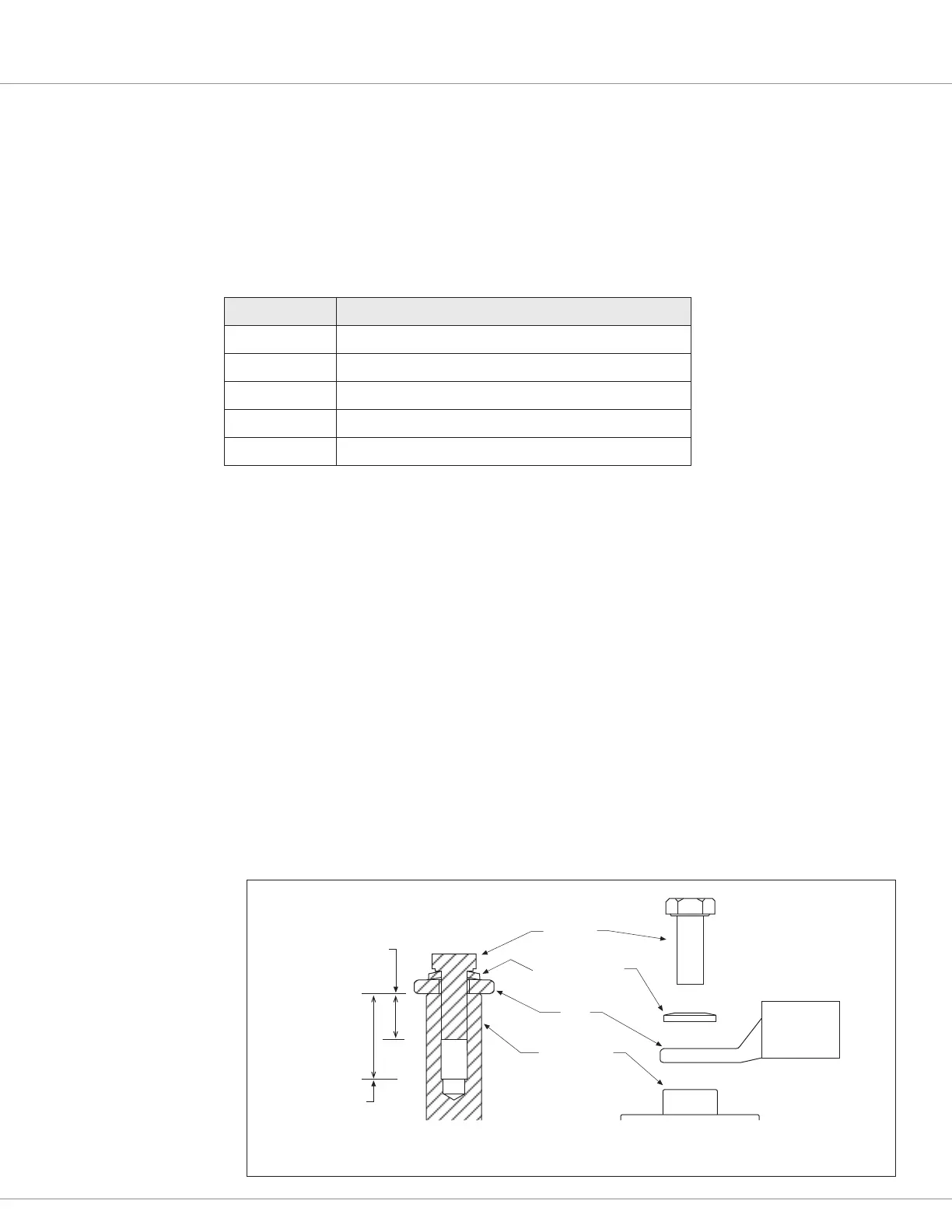
e high power connections are aluminum M6 terminals. Terminate the battery and motor cables
with high quality (tin-plated) copper lugs to match the application. Ensure the M6 bolts are the
proper length to meet the minimum thread depth engagement. Do not bottom-out the bolts in any
terminal. Follow Figure 7 connection guidelines:
• Place the lug on top of the aluminum terminal, followed by a high-load safety washer with its
convex side on top. e washer should be a SCHNORR 416320, or equivalent.
• For terminal connections with more than one lug, stack them so the lug carrying the least
current is on top.
• Ensure the clamping bolt is within the minimum and maximum depth when assembled.
• Tighten the assembly to 10.2 ±1.1 Nm (90 ±10 in-lbs.).
When routing the battery cables between the battery and controller, run the positive and negative
battery cables close to each other, avoiding pinch-points and areas of possible cable abrasion.
Typically, the positive cable is red and the negative cable is black. e motor phase cables are oen
black, yet clearly labeled at both ends. Reference Appendix B, Vehicle Design Considerations for
EMC guidelines.
Figure 7
Battery Power
and Motor
Phase Terminal
Connections
M6 BOLT
HIGH LOAD
SAFETY WASHER
LUG
M6 TERMINAL
SECTION VIEW
HIGH POWER TERMINALS
EXPLODED VIEW
10 mm MIN
DEPTH
18 mm
MAX
DEPTH

 Loading...


