2 — INSTALLATION AND WIRING
Curtis AC F2-A, F4-A, F6-A Motor Controllers – FOS 4.5 – April 2022 Return to TOC
pg. 16
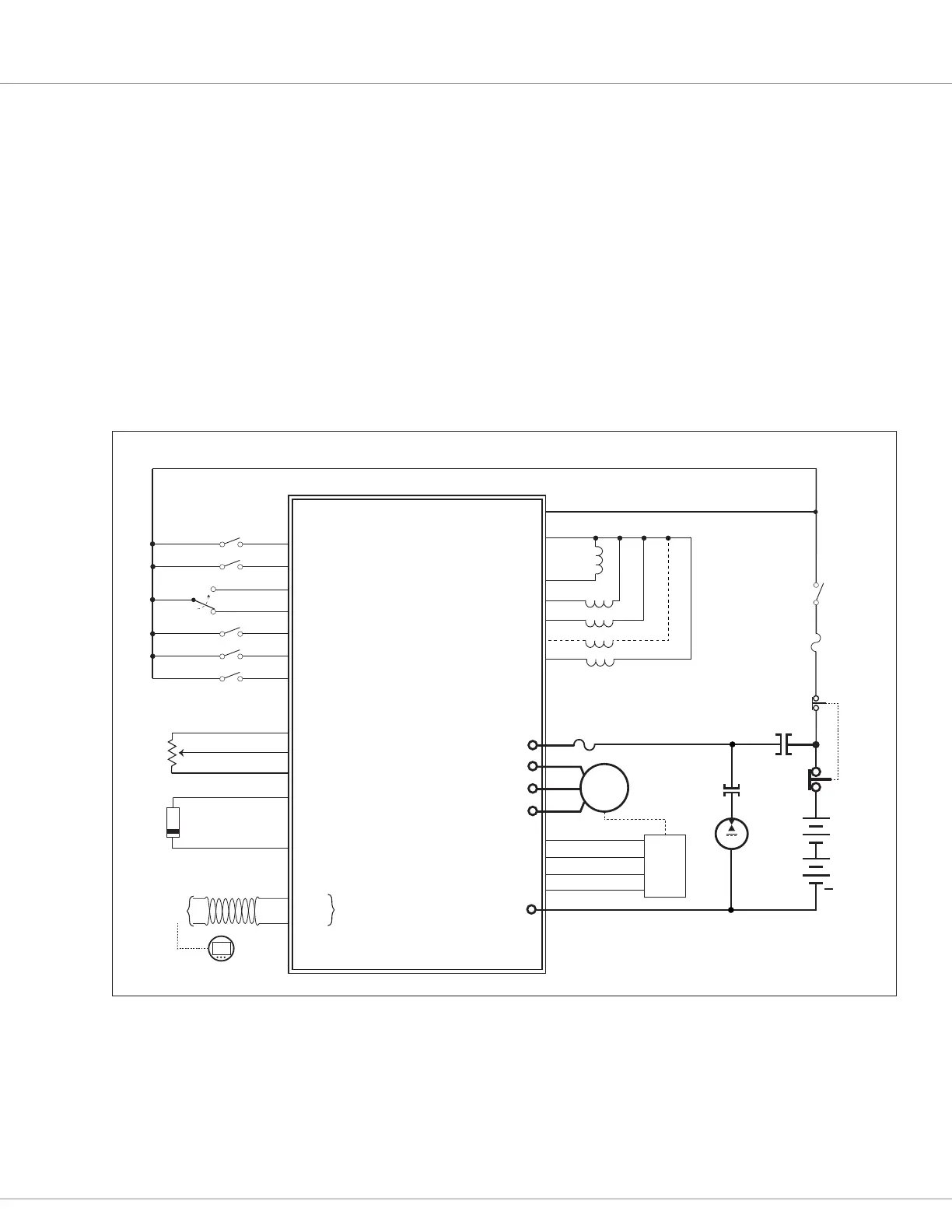
Controller Wiring Diagram (Examples)
The basic wiring diagrams for a Class III pallet truck use wired inputs from switches and
potentiometers, driving the traction motor. e Interlock, Forward, Reverse, Li, Lower, and the
redundant Emergency Reverse inputs are by external mechanical switches pulled to KSI (B+).
The traction motor feedback shall match the motor technology. The throttle input is a 3-wire
potentiometer (which meets EEC fault protection). Beyond these assigned I/O usages, the available
(non-assigned) switch inputs, drivers, and the analog output, are programmable to suit a diverse
range of the controller applications.
e F4/6-A illustrates both the non-isolated and isolated CAN port options. See Appendix E for
the controller models and specications, which support these options. e F2-A does not oer an
isolated CAN port option.
Quick Links:
Appendix E p.262
SWITCH 11 / ENC1_C
SWITCH 12
J1-21
SWITCH 13
J1-22
LOWER
SWITCH 14 / ANALOG 14 / +12V
J1-23
J1-7
J1-6
J1-3
J1-4
J1-5
J1-2
DRIVER 4 / SWITCH 24
DRIVER 5 / SWITCH 25
DRIVER 2 / SWITCH 22
DRIVER 3 / SWITCH 23
KSI COIL RETURN
MAIN
EM BRAKE
J1-1
KSI
ROTOR
POSITION
SENSOR
J1-16
INTERNAL 120Ω
TERMINATION IS
MODEL BASED
LIFT
B+
V
+5V
U
W
B−
CAN L
CAN H
PUMP
DRIVER 1 / SWITCH 21
J1-18
PHASE-B, Cos
ENC1_B, Cos
J1-17
ENC1_A, Sin
J1-12
I/O GROUND
GND
5V
CAN
PORT
J1-13
J1-20
ANALOG 2 / SWITCH 2 / MOTOR TEMP
I/O GROUND
MOTOR
TEMPERATURE
SENSOR
Note: KTY sensor shown.
The banded end must be
connected to I/O Ground.
J1-19
EMR_N.O.
EMR_N.C.
EMERG. REV
REVERSE
FORWARD
INTERLOCK
J1-15
J1-14
J1-8
SWITCH 8 / ANALOG 8
SWITCH 7 / ANALOG 7
SWITCH 5 / ANALOG 5
WIPER
I/O GROUND
SWITCH 6 / ANALOG 6 / POT HI
SWITCH 1 / ANALOG 1 / POT WIPER
J1-10
J1-11
J1-12
J1-9
J1-12
AC F2-A CONTROLLER (23-PIN)
AC
MOTOR
FUSE
PROP. VALVE
THROTTLE
Curtis 3140/1 CAN-based Gauge
MAIN
STOP
BATTERY
KEYSWITCH
FUSE
+
Pump
~
PHASE-A, Sin
Figure 12
AC F2-A Basic Wiring Diagram

 Loading...


