APPENDIX A
pg. 249
Return to TOC Curtis AC F2-A, F4-A, F6-A Motor Controllers – FOS 4.5 – April 2022
Example for TPDO Mapping with the Programmer
For this example, we will be setting up TPDO1 for the Node ID 0x26, and map Keyswitch_Voltage
and User2.
Make sure that the node is pre-operational. If not, send an NMT message using PCAN-view (or a
similar CAN dongle and soware).
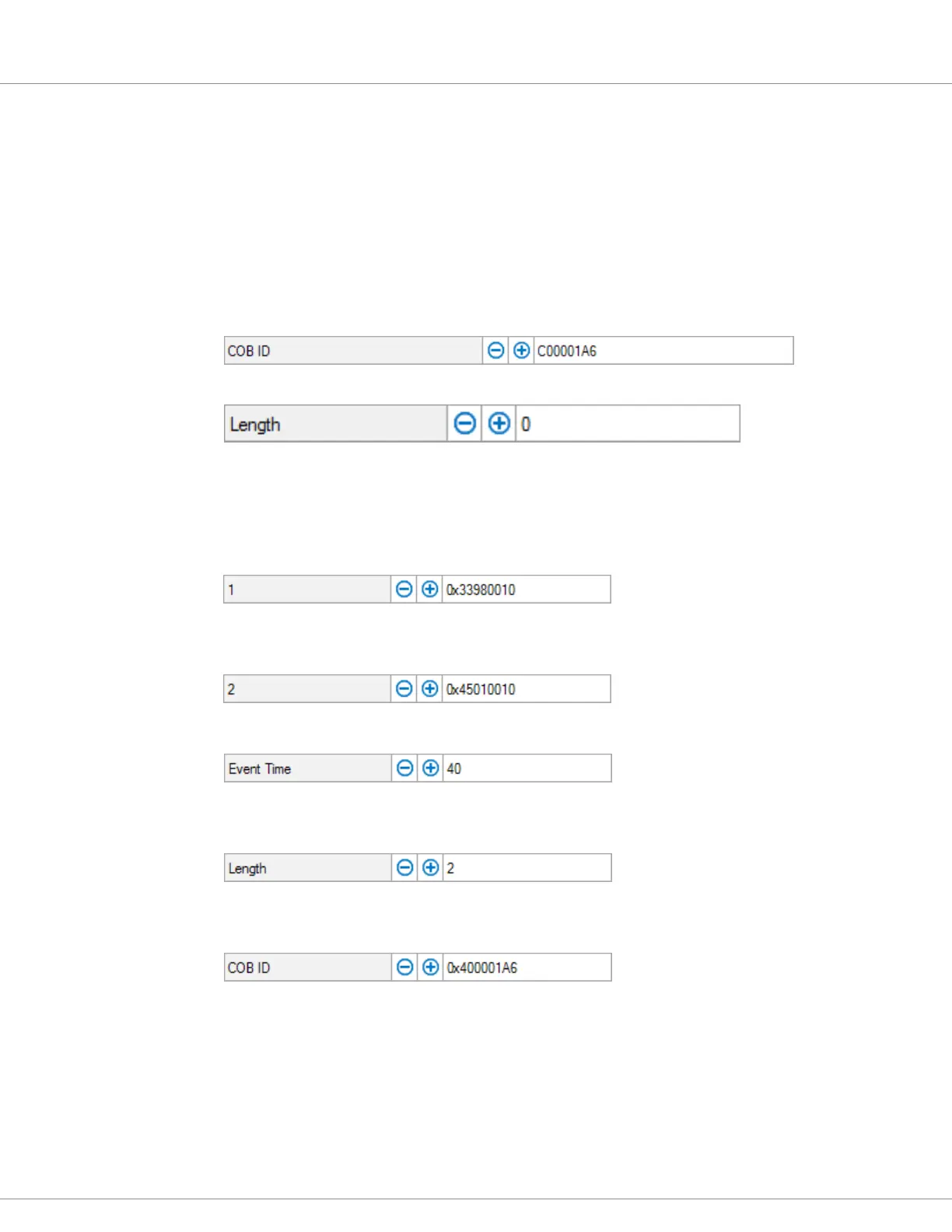
e rst step is to disable TPDO1. Do this by setting the most signicant bit of can_ tpdo_1_cob_id
to true (true = 1). Navigate in the CIT Programmer to the following location: Application Setup »
CAN Interface » PDO Setups. Set can_tpdo_1_cob_id to 0xC00001A6. (Note, for the TPDO, the
MSB is 1100 = Ch. See TPDO COB ID table, above).
Next, disable the mapping of TPDO1 by setting can_tpdo_1_length to 0.
Map the 16-bit Keyswitch_Voltage variable with CAN-object 0x3398.00, by setting can_tpdo_1_
map_1 to a value of 0x33980010. Note that when setting up a PDO that writes to an Operating System
variable, the complete word must be written at once (32-bit write to 32-bit variable, 16- bit write
to 16-bit variable). Input all values in hex. In this example, the 16-bit Keyswitch_Voltage variable’s
length is 10h.
Map 16 bits of the 32-bit User2 variable with CAN-object 0x4501.00, by setting can_tpdo_1_ map_1
to a value of 0x45010010. In this example, the 16-bits of User2 variable’s length is 10h.
Set can_tpdo_1_event_timer to a value in milliseconds, to set the transmit period.
Set can_tpdo_1_length to the number of variables (not bytes) that are mapped. at is 2 in
this example.
Now, the PDO can be re-enabled by setting can_tpdo_1_cob_id to value 0x4000001A6 (i.e., the 31st bit
is changed from 1 to 0 for Enabled, setting the MSB to 0100b = 4h. See TPDO COB ID table, above).
e TPDO will become active when changing the NMT State to Operational.
Follow this format for mapping TPDO2 - 4, matching the message type (3rd byte) number, while
retaining the same Node ID. For example, for Node ID = 0x26:
TPDO1 ... C00001A6 = disabled, 400001A6 = enabled
TPDO2 ... C00002A6 = disabled, 400002A6 = enabled
TPDO3 ... C00003A6 = disabled, 400003A6 = enabled
TPDO4 ... C00004A6 = disabled, 400004A6 = enabled

 Loading...


