4 — PROGRAMMABLE PARAMETERS
pg. 55
Return to TOC Curtis AC F2-A, F4-A, F6-A Motor Controllers – FOS 4.5 – April 2022
SPEED MODE/RESPONSE — FINE TUNING MENU
PARAMETER ALLOWABLE RANGE DEFAULT DESCRIPTION
HS (High Speed)
HS
0x3107 0x00
0 – 100 %
0 – 32767
70 % Sets the percentage of the Typical Max Speed above which the
HS parameters will be used.
See Figures 16 and 17 (below).
LS (Low Speed)
LS
0x3109 0x00
0 – 100 %
0 – 32767
30 % Sets the percentage of the Typical Max Speed below which the LS
parameters will be used.
See Figures 16 and 17 (below).
Max Speed Accel
Max_Speed_Accel_SpdM
0x3836 0x00
0.1 – 30.0 s
100 – 30000
1.0 sec In some applications the Max Speed value is changed frequently
through VCL or over CAN (PDOs). The Max Speed Accel parameter
controls the rate at which the maximum speed setpoint is allowed
to change when the value of Max Speed is raised. The rate set
by this parameter is the time to ramp from 0 rpm to Typical Max
Speed rpm.
For example, suppose the Max Speed is raised from 1000 rpm
to 4000 rpm. If the Typical Max Speed is 5000 rpm and the rate
is 10.0 seconds it will take 10.0 * (4000-1000) / 5000 = 6.0
seconds to ramp from 1000 rpm to 4000 rpm.
Max Speed Decel
Max_Speed_Decel_SpdM
0x3837 0x00
0.1 – 30.0 s
100 – 30000
10.0 sec This parameter works like the Max Speed Accel parameter except
that it controls the rate at which the maximum speed setpoint is
allowed to change when the value of Max Speed is lowered.
For example, suppose the Max Speed is decreased from 4500
rpm to 2500 rpm. If the Typical Max Speed is 5000 rpm and the
rate is 5.0 seconds it will take 5.0 * (4500-2500) / 5000 = 2.0
seconds to ramp from 4500 rpm to 2500 rpm.
Reversal Soften
Reversal_Soften
0x310B 0x00
0 – 100 %
0 – 3000
20 % Larger values create a softer reversal from regenerative braking
(regen) to drive when near zero speed. This helps soften the
transition when the regen and drive current limits are set to
different values.
Note: This parameter is not mode-specic.
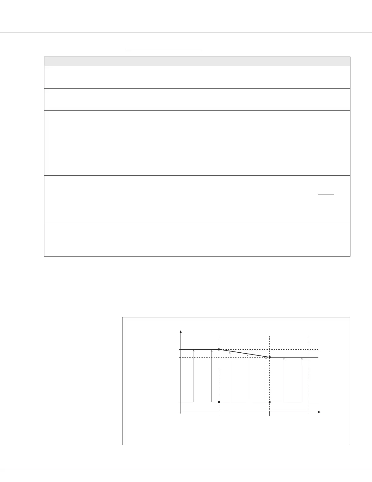
ACCEL RATE
(seconds)
MOTOR SPEED
LOW SPEED
FASTER
Full Accel Rate LS = 1.5
Full Accel Rate HS = 3.0
Low Accel Rate = 20.0
HIGH SPEED
TYPICAL MAX
SPEED
FASTER
90% Throttle
10% Throttle
INCREASING THROTTLE
(LS x Typical_Max_Speed)
= 30% x 5000 rpm = 1500
(HS x Typical_Max_Speed)
= 70% x 5000 rpm = 3500
Figure 16
Acceleration Response
Rate Diagram.
In this example,
HS = 70 %,
LS = 30 %,
Typical Max Speed = 5000 rpm

 Loading...


