2 — INSTALLATION AND WIRING
Curtis AC F2-A, F4-A, F6-A Motor Controllers – FOS 4.5 – April 2022 Return to TOC
pg. 22
Analog Inputs
The controllers support a variety of analog inputs. The input’s allowable voltage range varies
depending on the primary purpose of the input. Select the analog input that matches the application.
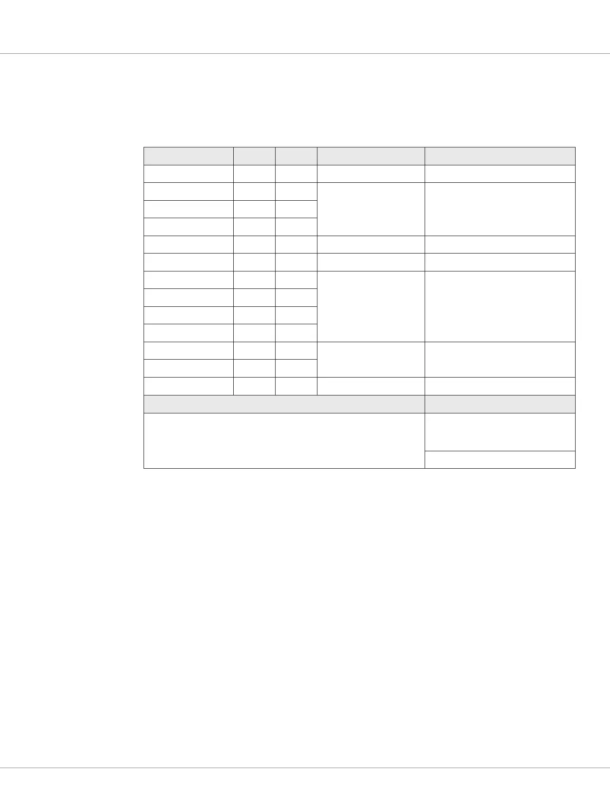
Table 9 Analog Inputs Electrical Specifications
Input/Signal Name 23-Pin 35-Pin Measurement Range
1,3
Input Impedance (± 10%)
Analog 1 11 16
0 – 10 Volts 20k Ω (potentiometer)
Analog 2 9 8
0 – 5 Volts 5k Ω (Enc/Sin/Cos/Temp)
Analog 3 17 31
Analog 4 18 32
Analog 5 8 9
0 – 20 Volts 5k Ω
Analog 6 10 15
0 – 10 Volts 20k Ω (potentiometer)
Analog 7 14 22
0 – 20 Volts 5k Ω
Analog 8 16 33
Analog 9 n/a 24
Analog 14 23 25
Analog 18 n/a 17
0 – 10 Volts 20k Ω (potentiometer)
Analog 19 n/a 27
Analog 31 n/a 26
0 – 20 Volts 5k Ω
VCL Functions VCL Monitor Variables
2
Analog_Input_Volts_X
Analog_Input_Percent_X
Pot_X_Resistance
(X = analog input#)
1
The measurement margin is +4% / –0% margin. This is for analog usage.
The full-scale accuracy is ± 2% over temperature (referenced to room temperature, 25°C).
The input signal filter is > 1 kHz for standard and pot inputs, > 40 kHz for encoder & sin/cos inputs.
2
When using potentiometer inputs, due to the dynamic tests (see text, below), the voltage reading is not constant. Use the input
percent variable for the throttle or controls value.
3
Increase voltage normalization range (analog_input_x_high) maximum limit to 30V for analog inputs, such that they can be used
as digital (switch) inputs without causing a voltage out-of-range fault.

 Loading...


