130 Section 8 Component Testing and Adjustment TP-6356 4/12
8.9.5 Oil Pressure Sender Testing
Disconnect the oil pressure sender lead 7C. See
Figure 8-10. Check the sender resistance with an
ohmmeter. Compare the resistance values when the
generator set is shut down and when it is running at
operating temperature to the values shown in S ection 1,
Specifications.
Use a mechanical oil pressure gauge to further verify
correct readings.
TP-5353-7
Lead 7C
Figure 8-10 Oil Pressure Sender, Typical
8.9.6 Water Temperature Sender
Testing
The water temperature sender has three configurations:
(1) a single function, single-terminal type, (2) a single
function, two-terminal type, and (3) a dual function, two
-terminal type with temperature gauge sender and low
coolant temperature switch. See Figure 8-11.
TP-5353-7
Lead 5
55
N
35A
Type 1 Type 2 Type 3
Figure 8-11 Water Temperature Sender, Typical
Sender type 3 has lead 5 connected to water
temperature sender terminal with a 6-32 screw and
lead 35A connected to the low water coolant
temperature switch terminal with an 8-32 screw.
Disconnect the water temperature sender lead 5 (and
lead N with type 2 configurations). Check the sender
resistances with an ohmmeter. Compare the resistance
values when the generator set is shut down and when it
is running at operating temperature to the values listed
in Section 1, Specifications.
8.10 Digital Interface (Circuit)
Boards B-354647/C-354647
(Decision-Makerr 3+ Controller)
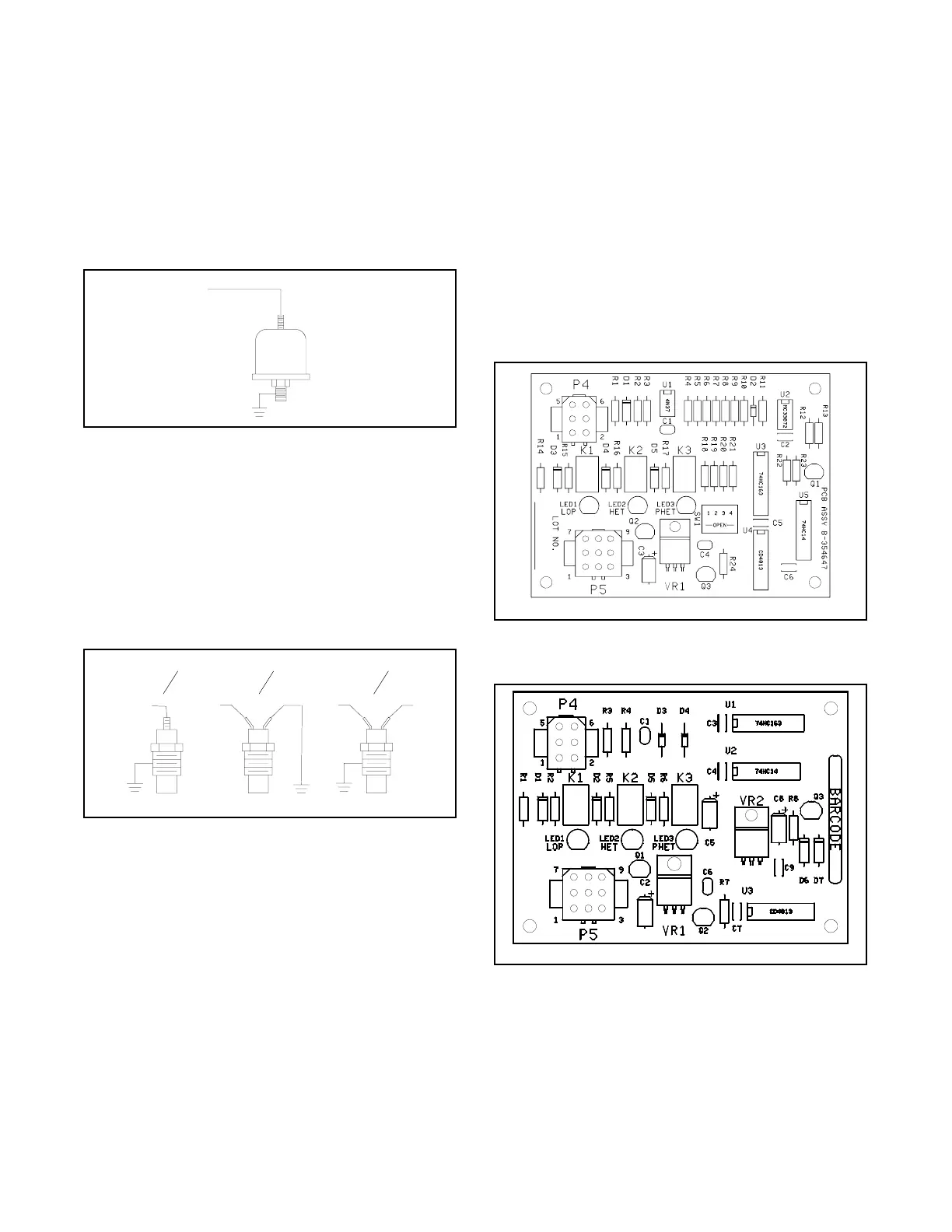
The generator sets using DDC Series 60/2000/4000
engines and DDEC engine controls use a digital
interface (circuit) board (DIB) to convert a 12 to 2 engine
speed pulse to work with the 16-light controller. In
addition, other selected engine switches communicate
with the 16-light controller. This allows the generator set
controller to obtain engine information from the DDEC
rather than from additional sensors/switches on the
engine. The DIB is shown in Figure 8-12 (B-354647)
and Figure 8-13 (C-354647). The C-354647 circuit
board does not use the 4-position DIP switch.
B-354647-
ABCD
Figure 8-12 Digital Interface (Circuit) Board (DIB)
B-354647
C-354647-B
Figure 8-13 Digital Interface (Circuit) Board (DIB)
C-354647

 Loading...


