136 Section 8 Component Testing and Adjustment TP-6356 4/12
Servicing the generator set when it is operating. Exposed
moving parts can cause severe injury or death. Keep
hands, feet, hair, clothing, and test leads away from the belts
and pulleys when the generator set is running. Replace
guards, screens, and covers before operating the generator
set.
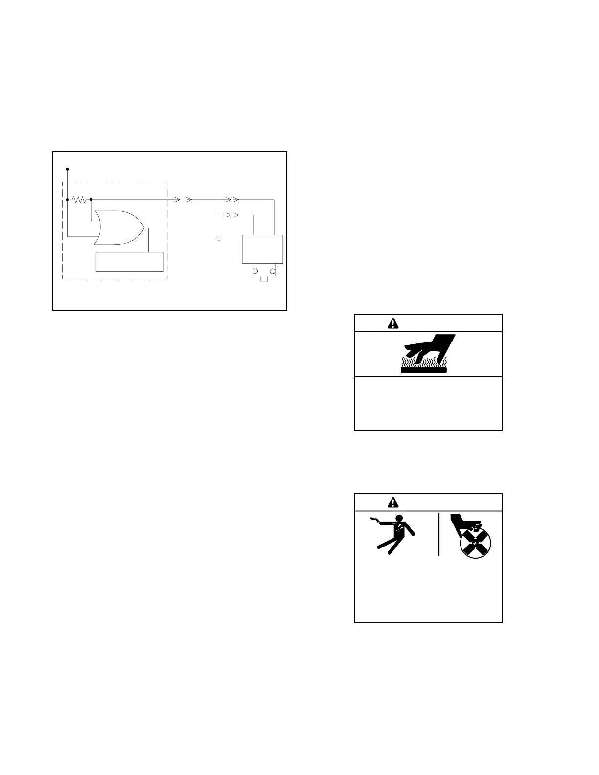
LWL fault shutdown does not function during the first
30 seconds after startup. See Figure 8-25 for
connections.
SB-554
Sender
Microprocessor
Comparator
B
Load Resistor
B+ (12 VDC)
P1-10
31A
Microprocessor
Circuit Board
Figure 8-25 2-Wire Low Water Sender
1. Measure the DC voltage between lead 31A (+) and
ground (--) with the sender submerged in coolant.
The voltmeter indicates approximately 12.5 VDC
with a functioning sender.
2. Measure the DC voltage between lead 31A (+) and
ground (--) with the sender removed from the
coolant for at least 5-15 seconds. The voltmeter
indicates a voltage drop to approximately 7 VDC
with a functioning sender.
Consider the sender defective:
D If the DC voltage between lead 31A (+) and
ground (--) is 7 VDC or less with the sender
submerged in coolant and the voltage rises to
12 VDC after disconnecting lead 31A from the
sender.
D If the DC voltage between lead 31A (+) and
ground (--) remains constant with the sender
submerged in coolant and then removed for at least
5-15 seconds.
Consider the main circuit board defective:
D If the DC voltage between lead 31A (+) and
ground (--) remains at 7 VDC with and without
connection to the sender.
8.13.2 3-Wire Sender
Function
The 3-wire low water level (LWL) sender is a resistance
device. Lead 70 supplies 12 or 24 VDC (+ ) engine
electrical supply voltage and lead N is a ground
connection. The sender has the operating voltage
stamped on the sender hex surface. Lead 31 is the
output to the controller logic. The sender detects the
absence of coolant at the probe tip and signals the
condition of a short circuit to ground.
Lead 31 (blue) signals an open circuit to ground when
the sender probe tip senses coolant present and signals
a short circuit to ground when the sender probe tip
senses no coolant present.
Testing
Use the following test procedure for the 3-wire low water
level sender while the generator set operates. All leads
must remain connected to the sender during the test.
Hot engine and exhaust system.
Can cause severe injury or death.
Do not work on the generator set until
it cools.
WARNING
Servicing the exhaust system. Hot parts can cause
severe injury or death. Do not touch hot engine parts. The
engine and exhaust system components become extremely
hot during operation.
Hazardous voltage.
Can cause severe injury or death.
Operate the generator set only when
all guards and electrical enclosures
areinplace.
Moving parts.
WARNING
Servicing the generator set when it is operating. Exposed
moving parts can cause severe injury or death. Keep
hands, feet, hair, clothing, and test leads away from the belts
and pulleys when the generator set is running. Replace
guards, screens, and covers before operating the generator
set.

 Loading...


