148 Section 8 Component Testing and Adjustment TP-6356 4/12
8.20 Speed Sensor
The speed sensor is found on permanent magnet (PM)
and wound field (WF) alternators. The speed sensor is
located on the alternator end bracket. Several styles are
used, but they are all functionally the same.
Follow the procedure outlined below to determine if the
speed sensor (overspeed fault) is emitting a signal.
8.20.1 Speed Sensor Test with Generator
Set Running
1. With the generator set master switch in the
OFF/RESET position, connect a DC voltmeter
between the positive (+) lead (wire 24) at the speed
sensor and the ground (wire 2). The voltmeter
should read approximately 8--12 volts DC.
2. Place the generator set master switch in the RUN
position to start the generator set.
3. With the generator set running, connect a DC
voltmeter negative probe to the 0 terminal
(wire 16—white) on the speed sensor. Place the
voltmeter positive probe on the positive (+) terminal
(wire 24—red). The voltmeter should indicate
approximately 7--12 volts DC.
During the test, the controller leads must remain
connected to the speed sensor terminals. Slide
leads from speed sensor terminals only enough to
expose connection for test leads. Do not
disconnect the leads.
4. Place the generator set master switch in the
OFF/RESET position to stop the generator set.
5. If the speed sensor is emitting a signal, check the
continuity of the speed sensor leads (wires 2, 16,
and 24) between the controller P1 connector and
the lead terminals at the speed sensor.
If the speed sensor is not emitting a signal, go to
Section 8.20.2, Speed Sensor Test with Separate
12 VDC Source.
8.20.2 Speed Sensor Test with Separate
12 VDC Source
Test the speed sensor using the following procedure. It
is NOT necessary to remove the speed sensor from the
end bracket.
1. Place the generator set master switch in the
OFF/RESET position.
2. Disconnect the speed sensor leads.
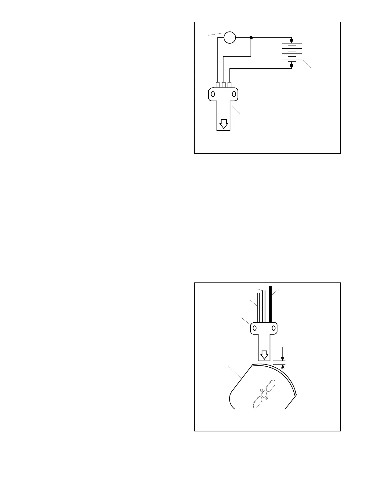
3. Connect speed sensor, DC voltmeter, and DC
voltage source as shown in Figure 8-46.
+
---
+
1
2
3
TP-5353-7
1. DC voltmeter
2. 12-volt battery or DC power supply
o + ---
3. Sensing surface
Figure 8-46 Speed Sensor Test
4. Touch sensing surface with a flat piece of iron or
steel at least 4.1 cm (1/4 cu. in.) in size.
5. The DC voltmeter test reading should equal the
source voltage, approximately 12 VDC.
6. Remove the iron or steel piece from the sensing
surface and observe a voltmeter reading of 0 VDC.
7. If the speed sensor passes steps 5 and 6, the
speed sensor is functional. Replace the speed
sensor if it fails the test.
8. Connect the speed sensor leads and adjust the air
gap. See Figure 8-47.
4. Wire 2: black
5. Air gap
6. Magnetic actuator
0.36--0.71 mm
(0.014--0.028 in.)
TP-5353-8
1. Speed sensor
2. Wire 16: white/clear
3. Wire 24: red
1
2
3
4
5
6
o+--
Figure 8-47 Speed Sensor Air Gap

 Loading...


