58 Section 3 Decision-Makerr 3+ Troubleshooting TP-6356 4/12
3.6.3 FASTCHECKr Diagnostic Tool
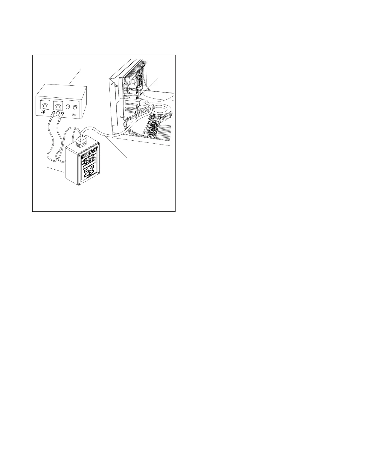
1. Unplug the DC engine harness from the DC
harness connector (P1). See Figure 3-25.
R11118-2
3-187
1. FASTCHECK® diagnostic tool
2. Wiring harness
1
2
3
4
3. DC harness connector
4. DC power supply
Figure 3-25 FASTCHECK
®
Connections
2. Connect the FASTCHECK
®
harness to the DC
harness connector (P1) and to the top of the
FASTCHECK
®
.
3. Move the generator set master switch to the
OFF/RESET position.
4. Move the FASTCHECK
®
engine switch to the OFF
position.
5. Clip the red (+) and black (--) harness leads to a
battery(ies) or DC power supply that corresponds
to the generator set engine electrical system (12 or
24 volt). Adjust the output voltage to 1-2 volts
above the battery voltage when using a DC power
supply. Use generator set battery(ies) if accessible
and fully charged.
Note: Incorrect battery polarity may cause
controller circuit board damage when
connecting the FASTCHECK
®
.
Note: Because of the absence of AC output, the
auxiliary lamp flashes during controller
testing. The NOT IN AUTO lamp illuminates
whenever the generator set master switch is
not in the AUTO position.
6. Move the generator set master switch to the RUN
position. Move the FASTCHECK
®
engine switch
to CRANK. The FASTCHECK
®
IGN., CRK., and
REG. lamps should light. The generator set
controller causes the engine to crank until the
FASTCHECK
®
switch is moved to RUN (or
OVERCRANK shutdown appears on generator set
controller).
7. Move the FASTCHECK
®
engine switch to RUN.
The CRK. lamp should go out and the REG. and
IGN. lamps should stay on.
8. Simulate engine malfunctions by pressing the
FASTCHECK
®
fault switches. The corresponding
fault lamp on the controller should light during each
simulated engine malfunction.
Leave the FASTCHECK
®
engine switch in the
RUN position for at least 30 seconds before
pushing the toggle switches. Toggle the generator
set master switch to OFF/RESET and the
FASTCHECK
®
engine switch to OFF, then back to
RUN after simulated fault shutdowns.
9. Use the following sections to test overcrank
circuitry, speed sensor circuitry, and generator set
condition indicators.
3.6.4 Overcrank
The following procedure tests the overcrank function on
the generator set controller and the ability to:
D Detect a locked engine.
D Stop a startup attempt if the starter locks or will not
engage.
If the OVERCRANK shutdown fails to function, check
the speed sensor and related circuitry. See
Section 3.6.5, Controller Speed Sensor Circuitry, and
Section 8.20, Speed Sensor Test.
1. Move the FASTCHECK
®
engine switch to the OFF
position.
2. Move the generator set master switch to the OFF
position and then move the switch to the RUN
position.
3. The IGN., CRK., and REG. lamps on the
FASTCHECK
®
should light for approximately
5 seconds and then go out. Then 5 seconds later
the IGN., CRK.,and REG. lamps should relight for
5 seconds before going out again (15 seconds total
elapsed time). The controller OVERCRANK lamp
lights.
4. Check for operating voltage between terminals
TB1-42A (+) and TB1-12 (--).

 Loading...


