137Section 8 Component Testing and AdjustmentTP-6356 4/12
LWL fault shutdown does not function during the first
30 seconds after startup. See Figure 8-26 for
connections.
273520
Figure 8-26 3-Wire Low Water Sender
1. Measure the resistance between lead 31 and
ground with the sender submerged in coolant. The
ohmmeter indicates a high resistance reading with
a functioning sender.
2. Measure the resistance between lead 31 and
ground with the sender removed from the coolant
for at least 5-15 seconds. The ohmmeter indicates
a low resistance reading with a functioning sender.
Consider the sender defective:
D If the ohmmeter reading between lead 31 (blue) and
ground remains constant with the sender submerged
in coolant and then removed for at least 5-15
seconds.
D If the ohmmeter reading between lead 31 and ground
indicates low resistance with the sender submerged
in coolant.
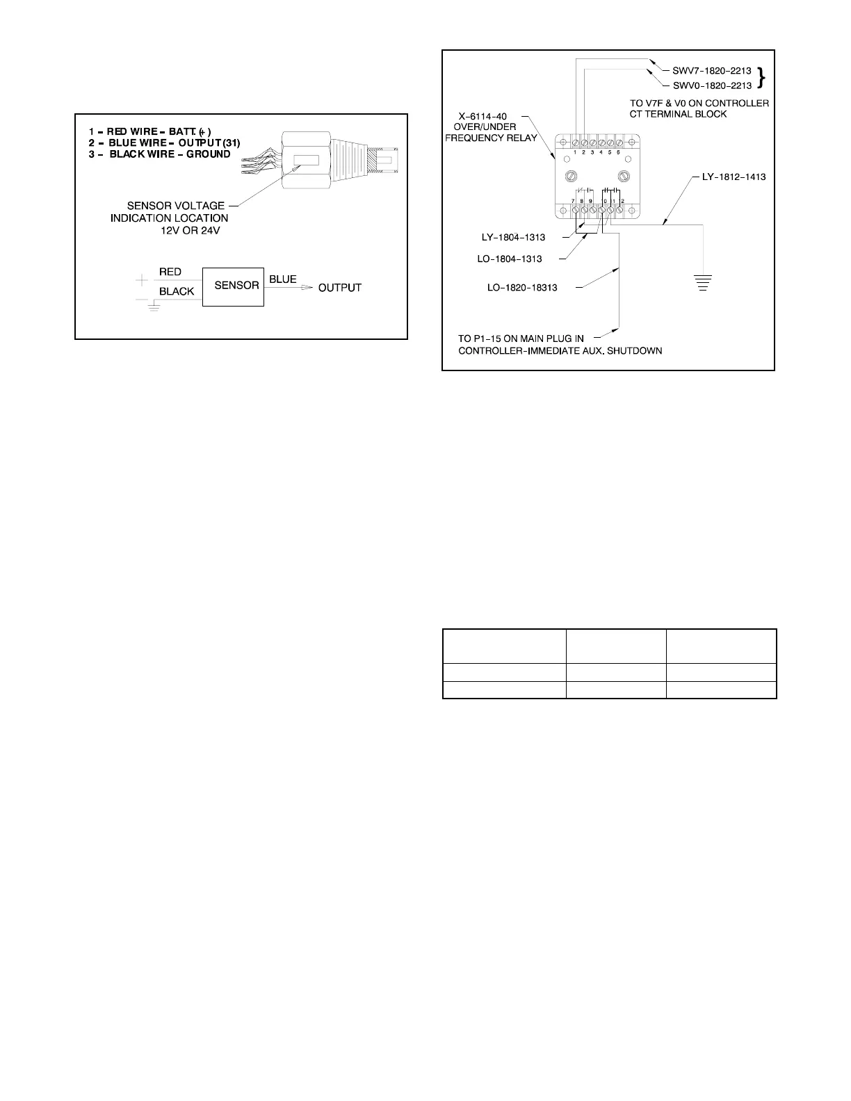
8.14 Over/Underfrequency Relay
(Decision-Makerr 3+ Controller)
8.14.1 Function and Connection
The over/underfrequency relay kit provides frequency
protection when required. This kit mounts inside the
controller with sensing connections to the CT terminal
block and output to auxiliary shutdown at P1-15. Use
the following procedure to set the shutdown points. See
Figure 8-27.
Note: This over/underfrequency relay kit is not
compatible with generator sets using electronic
engine controls without a frequency adjustment
provision.
JK-272000-A
Figure 8-27 Over/Underfrequency Relay
8.14.2 Overfrequency Adjustment
1. Turn the overfrequency adjustment potentiometer
fully clockwise (CW).
2. Place the generator set master switch to the RUN
position to start the generator set.
3. Adjust governor. See engine operation manual,
engine service manual, or the appropriate
governor section of this manual for governor
adjustment procedure. See Figure 8-28.
Specification
Type
Overfrequency
Hz
Underfrequency
Hz
Standard 63 57
FAA 61.5 58.5
Figure 8-28 Over/Underfrequency Relay Specs
4. Slowly turn overfrequency potentiometer
counterclockwise (CCW) until the LED starts
flashing. After approximately 10 seconds, the
generator set will shut down on auxiliary fault.
5. Place the generator set master switch to the
OFF/RESET position to reset the controller.
6. Place the generator set master switch to the RUN
position to start the generator set.
7. Readjust the governor to the desired frequency as
required.
8. Place the generator set master switch to the
OFF/RESET position to stop the generator set.

 Loading...


