176 Section 9 Gas Fuel Systems TP-6356 4/12
5. Change the engine ignition timing (30--60 kW
models only).
a. Loosen the distributor hold-down clamp screw.
b. Remove dirt and grease from the crankshaft
pulley groove and engine timing plate mark
using a clean rag. Highlight the timing marks
with chalk.
c. Connect an ignition timing light to the engine.
Follow the ignition timing light manufacturer’s
instructions.
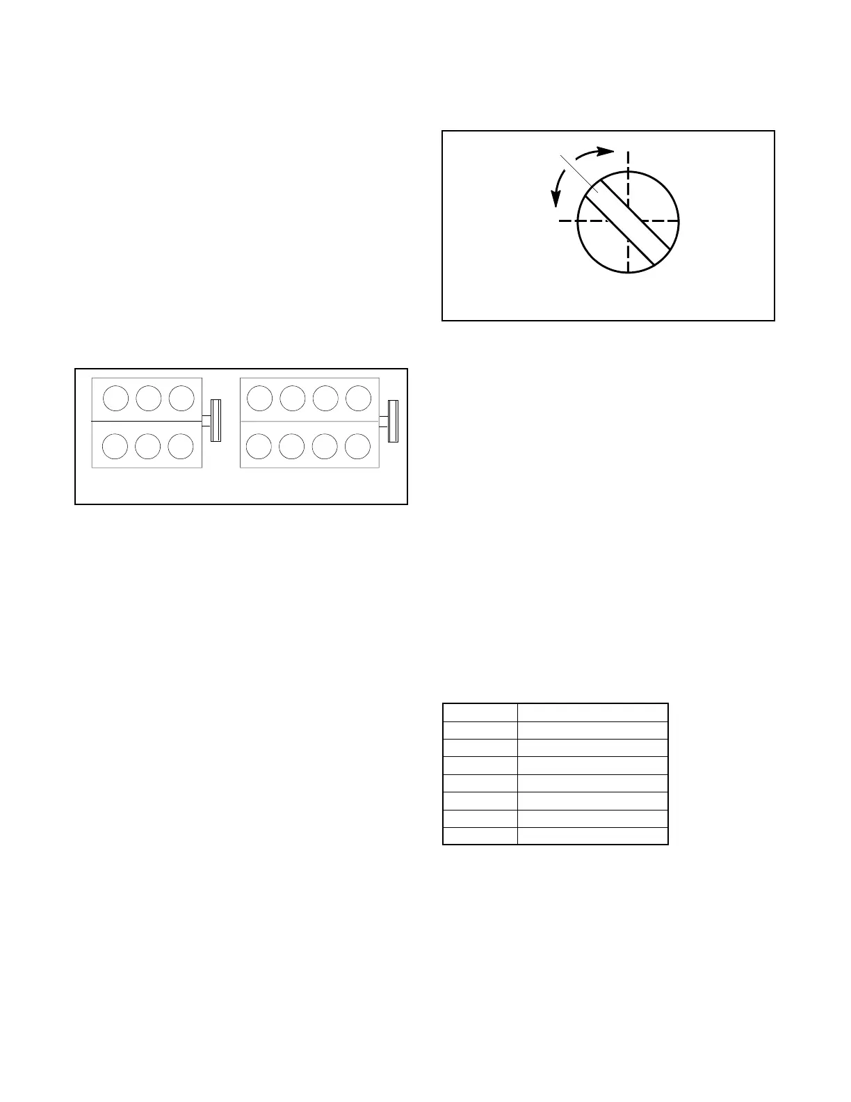
Typically the ignition timing light connects to the
starting battery for power and the inductive
pickup goes on the no. 1 spark plug wire. The
no. 1 spark plug is in the front left side of the
engine. See Figure 9-26.
TT-1295
11
30--45 kW 50/60 kW
Figure 9-26 Engine No. 1 Cylinder/Spark Plug
d. Set the ignition timing light adjustment to
28° BTDC (before top dead center) for LP gas
vapor.
e. Place the generator set master switch in the
RUN position to start the generator set.
f. Point the ignition timing light at the engine
timing plate mark and slowly turn the distributor
CW or counterclockwise (CCW) until the
crankshaft pulley groove aligns with the engine
timing plate mark.
g. Place the generator set master switch in the
OFF position to stop the generator set.
h. Tighten the distributor hold-down clamp to
25 Nm (18 ft. lb.) being careful not to alter the
distributor position.
i. Disconnect the ignition timing light from the
engine.
6. Adjust the gas mixer.
a. Place the generator set master switch in the
RUN position to start the generator set. Run
the generator set at approximately half load.
b. See Figure 9-22 for location of the fuel mixture
adjustment screw and adjust the fuel mixture
screw (Figure 9-27) until the engine runs
smoothly.
1
2
3
TP-5750-3
1. Fuel adjusting screw
2. Lean
3. Rich
Figure 9-27 Fuel Mixture Adjustment, Typical
c. Apply varying loads and readjust the mixer as
necessary to achieve s mooth engine
performance at all load levels.
d. Place the generator set master switch in the
OFF position to stop the generator set.
9.10 Fuel Mixture Adjustment with
Oxygen Sensor A-345052
(30--100 kW GM-Powered Models with
Barber-Colman Governor)
Adapted from Service Bulletin SB-615.
This section details fuel mixture adjustment for General
Motors engine-powered generator sets with Barber-
Colman governors. Figure 9-28 lists specification
numbers for generator sets with Barber-Colman
governors.
Model, kW Spec No.
30 GM13685-GA1, 4, 7, 10
35 GM13685-GA2, 5, 8, 11
45 GM13685-GA3, 6, 9, 12
50 GM13686-GA1, 3, 5, 7
60 GM13686-GA2, 4, 6, 8
80 GM13934-GA1, 2, 3, 4
100 GM13934-GA5, 6, 7, 8
Figure 9-28 Specification Numbers
Use the following procedure to field adjust the fuel
mixture on generator sets that are not California Air
Resources Board (CARB) or United States
Environmental Protection Agency (EPA) certified.
Correct fuel metering valve adjustment provides both
reliable c old starting and overall generator set
performance.

 Loading...


