138 Section 8 Component Testing and Adjustment TP-6356 4/12
8.14.3 Underfrequency Adjustment
1. Turn underfrequency adjustment potentiometer
fully clockwise (CW).
2. Place the generator set master switch to the RUN
position to start the generator set.
3. Adjust governor See engine operation, engine
service manual, or the appropriate governor
section of this manual for governor adjustment
procedure. See Figure 8-28.
4. Slowly turn underfrequency potentiometer
counterclockwise (CCW) until LED starts flashing.
After approximately 10 seconds, the generator set
will shut down on auxiliary fault.
5. Place the generator set master switch to the
OFF/RESET position to reset the controller.
6. Place the generator set master switch to the RUN
position to start the generator set.
7. Readjust the governor to the desired frequency as
required.
8. Place the generator set master switch to the
OFF/RESET position to stop the generator set.
8.15 Overvoltage Feature
(Decision-Makerr 3+ Controller)
8.15.1 Function and Application
The GM28725 main circuit board on Decision-Makerr
3+ controllers integrates an overvoltage protection
feature. The overvoltage feature provides overvoltage
protection when output voltage is 15% above nominal
voltage for more than one second. The factory-setting
of 15% above nominal voltage is field-adjustable.
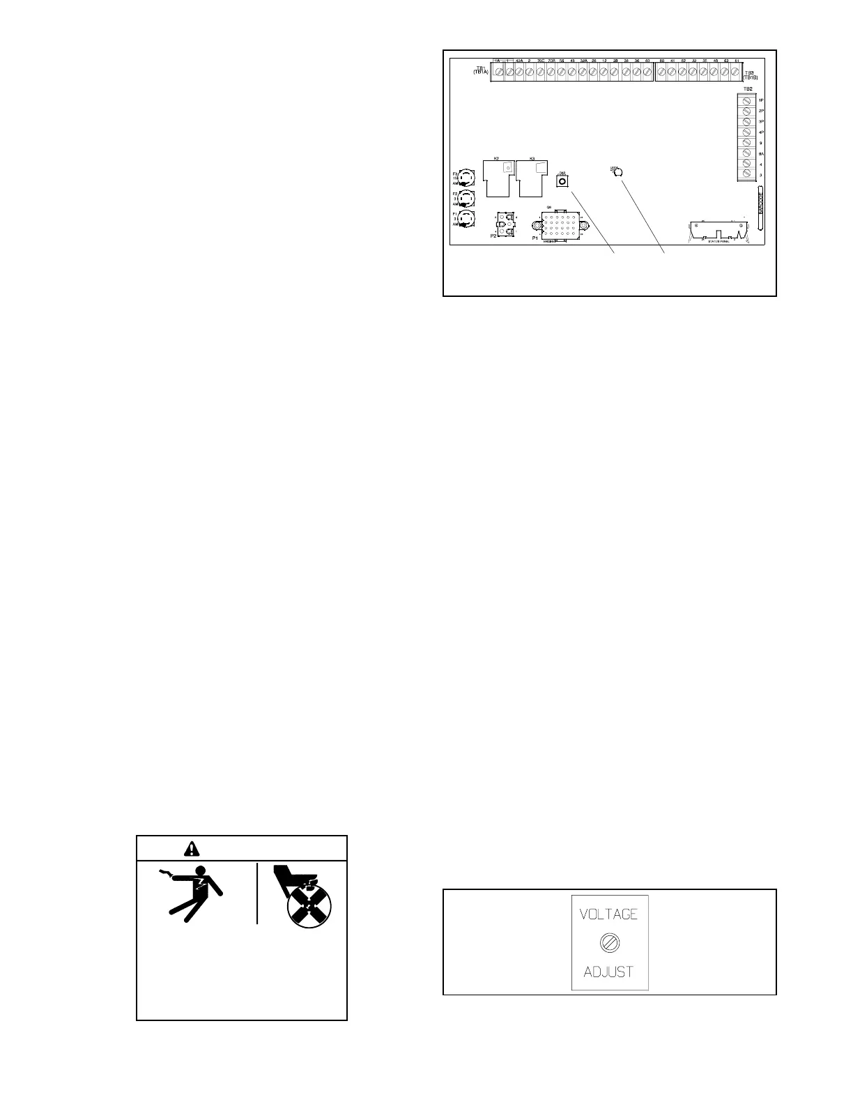
8.15.2 Testing and Adjustment
If the function of the overvoltage feature is questionable
or requires adjustment from the factory setting, perform
the following adjustment. See Figure 8-29.
Hazardous voltage.
Can cause severe injury or death.
Operate the generator set only when
all guards and electrical enclosures
areinplace.
Moving parts.
WARNING
GM28725-D-S
1. R42 overvoltage adjustment pot.
2. LED4 overvoltage shutdown
1 2
Figure 8-29 Overvoltage Adjustment Pot. R42
Disconnecting the electrical load. Hazardous voltage can
cause severe i njury or death. Disconnect the generator set
from the load by turning off the line circuit breaker or by
disconnecting the generator set output leads from the transfer
switch and heavily taping the ends of the leads. High voltage
transferred to the load during testing may cause personal
injury and equipment damage. Do not use the safeguard
circuit breaker in place of the line circuit breaker. The
safeguard circuit breaker does not disconnect the generator
set from the load.
1. Disconnect the generator set from the load by
opening the line circuit breaker (if equipped) or
disconnecting and heavily taping the output leads
(if not already done).
2. Determine the overvoltage shutdown value based
on the user requirement. The factory setting is 15%
above nominal line-to-neutral voltage with a
maximum value of about 200 volts.
3. Remove the controller cover.
4. Place the generator set master switch in the RUN
position to start the generator set.
5. Observe the controller AC voltmeter during this
step because the voltage reading just prior to
shutdown is the present overvoltage shutdown
point.
Turn the voltage adjustment potentiometer on the
controller front panel slowly CW until the generator
set shuts down. See Figure 8-30. The circuit board
LED4 lights and the controller auxiliary shutdown
lamp lights.
TP-6262-2
Figure 8-30 Controller Voltage Adjustment Pot.

 Loading...


