165Section 9 Gas Fuel SystemsTP-6356 4/12
Auto Changeover Natural Gas/LPG Vapor
Operation
D Disconnect lead 65 from N5.
D Connect lead N5 to LFP2 relay common terminal.
D Connect lead 73A to the fuel solenoid valve (natural
gas).
D Connect lead 73B to the fuel solenoid valve (LPG
vapor).
Eng.
ECM
Natural
Gas
LPG
Vapor
LPG
Liquid
Auto
Changeover
73A
QCON--7
(NG fuel
solenoid
valve)
not used
QCON--7
(NG fuel
solenoid valve)
N5 not used 65 65 LFP2--COM
73B not used QCON--10 (LPG fuel solenoid valve)
65 not used N5 N5 not used
63 LFP1--NC low fuel pressure sensor (if used)
70E2 P6--B (15 amp fuse)
Figure 9-3 Gas F uel Electrical Connections
9.1.4 Fuel System Changeover Kits
(Dual Fuel)
Automatic Changeover
A changeover fuel system kit provides automatic
changeover from natural gas to LPG vapor. The
primary and backup fuels each have a fuel solenoid
valve. The primary fuel is natural gas; the backup fuel
is LPG vapor. Before starting, both fuel solenoid valves
are closed. When the generator set starts, the primary
fuel solenoid valve opens. The primary fuel line has a
pressure switch in series with a relay connected to the
start/run circuit.
When the primary fuel pressure drops below 0.6 kPa
(1.4 oz./in.
2
) or 6.4 cm (2.5 in.) water column , a relay
opens the backup fuel solenoid valve and closes the
primary fuel solenoid valve. When the primary fuel
pressure rises above 0.6 kPa (1.4 oz./in.
2
)or6.4cm
(2.5 in.) water column, the generator set uses the
primary fuel. Contact an authorized service
distributor/dealer for kit availability.
Emissions certified models use a single electronic-
controlled pressure regulator (EPR) for both fuels. A tee
fitting connects both fuels together upstream of the
EPR. During operation when using the secondary fuel, it
is normal for a small amount of secondary fuel to seep
back through the primary fuel solenoid valve. To counter
this situation, one of two methods is used depending
upon the generator set model: (1) a second solenoid
valve (identical to the primary fuel solenoid valve) is
installed in a reverse configuration on the primary fuel
side or (2) a small vent line is installed between the
primary fuel inlet and the air intake through a fuel
solenoid valve.
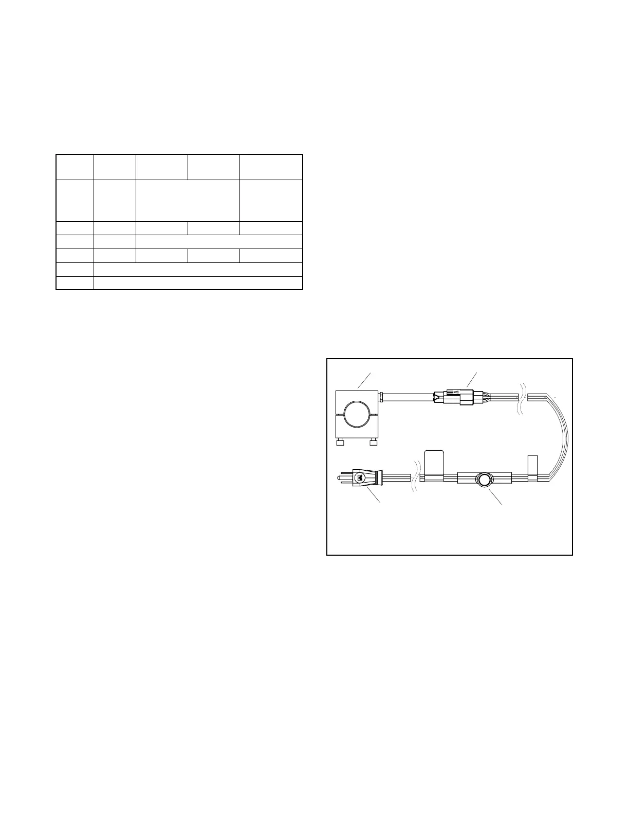
9.1.5 Crankcase Ventilation (CCV)
Heater Kit GM78171-KP1
(125/150REZG models)
The crankcase ventilation (CCV) heater kit provides a
controlled heating source to the crankcase ventilation
system preventing freezing water buildup during cold
weather. The thermostat turns on at 4_C(40_F) and
turns off at 16_C(60_F) reducing energy consumption.
SeeFigure9-4.
1. Heater element
2. Inline connector
3. Thermostat
4. AC power cord
TT-1560
1 2
3
4
Figure 9-4 Crankcase Ventilation Heater Kit

 Loading...


