134 Section 8 Component Testing and Adjustment TP-6356 4/12
8.11.3 Circuit Board Troubleshooting
The pulse converter circuit board contains an LED
indicator for diagnostic troubleshooting. See
Figure 8-20.
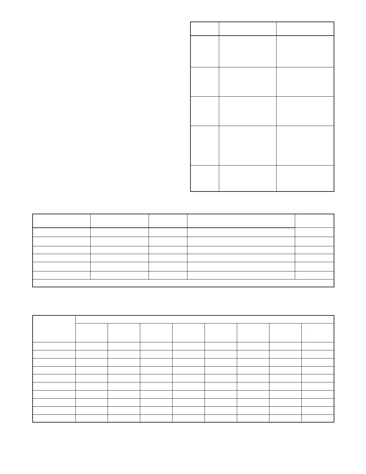
Figure 8-21 shows generator set models implementing
the pulse converter circuit board and Figure 8-22
indicates the pulse converter circuit board settings
based on the number of flywheel teeth.
LED
Indicator
Probable Causes Recommended Actions
Flashes
very fast
(greater
than 1 Hz)
DIP switch set at less
than 15 flywheel teeth
DIP switch setting does
not match flywheel
number of teeth
Reset the DIP switch to
match the engine
flywheel number of teeth
Flashes at
a1Hzrate
DIP switch set correctly.
Note: The distinction
between 1 Hz and 1.1
Hz, for example, is
visually unrecognizable.
Circuit board functionally
okay
Flashes
very slowly
(less than
1 Hz)
DIP switch setting does
not match flywheel
number of teeth
Reset the DIP switch to
match the engine
flywheel number of teeth
Off (red on,
black off)
DIP switch setting does
not match flywheel
number of teeth
No power to the circuit
board
Defective circuit board
Reset DIP switch
Check power source
Replace defective circuit
board
On
continuous
(steady)
DIP switch setting does
not match flywheel
number of teeth
Defective circuit board
Reset DIP switch
Replace defective circuit
board
Figure 8-20 Pulse Converter Circuit Board
Troubleshooting Chart
Generator Set Model Controller
Flywheel
Teeth, Qty.
Comments
J1 Shunt
Connection
200REOZV
550
NA Tach feature Pins 1--2
230/250REOZV
550
NA Tach feature and P5-9 air heater output feature Pins 1--2
275/300REOZV 16-light microprocessor NA P5-7 LOP and P5-8 AHCT alarms only NA
350/400REOZV 16-light microprocessor 38 (timing gear) P5-7 LOP and P5-8 AHCT alarms only Pins 2--3
500REOZV
550
NA Tach feature Pins 1--2
500REOZV 16-light microprocessor 153 Pins 2--3
NA not applicable
Figure 8-21 Generator Set and Number of Engine Flywheel Teeth
Flywheel Teeth,
Qty.
DIP Switch Position (1=Open , 0=Closed)
DIP 8
Switch
Value=128
DIP 7
Switch
Value=64
DIP 6
Switch
Value=32
DIP 5
Switch
Value=16
DIP 4
Switch
Value=8
DIP 3
Switch
Value=4
DIP 2
Switch
Value=2
DIP 1
Switch
Value=1
1 0 0 0 0 0 0 0 1
2 0 0 0 0 0 0 1 0
4 0 0 0 0 0 1 0 0
8 0 0 0 0 1 0 0 0
16 0 0 0 1 0 0 0 0
32 0 0 1 0 0 0 0 0
64 0 1 0 0 0 0 0 0
128 1 0 0 0 0 0 0 0
38 (timing gear) 0 0 1 0 0 1 1 0
153 1 0 0 1 1 0 0 1
Figure 8-22 Pulse Converter Circuit Board Settings Based on the Number of Flywheel Teeth

 Loading...


