TP-6356 4/1262 Section 4 Decision-Makerr 340 Controller
4.2 Controller Circuit Board
Service Kits GM37440 and
GM37441
Adapted from Installation Instruction TT-1391 8/04.
4.2.1 Introduction
The Decision-Makerr 340 controller circuit board
service kits replace the circuit boards shown in
Figure 4-2. See Figure 4-3 for identification of the
controller and Figure 4-4 for location and descriptions of
the controller circuit boards.
Service Kit Part
Number
Circuit Board
Part Number
Circuit Board
Description
GM37440 A--352166 Input conditioning
GM37441 A--352160 Interconnection
Figure 4-2 Circuit Board Service Kits
Figure 4-3 Decision-Makerr 340 Controller Front
View
4.2.2 Items Required
The following equipment is required to calibrate the
generator set after a new circuit board is installed.
D Resistive load bank rated for the generator set
standby rating
D RMS voltmeter and ammeter (some load banks may
include metering)
D TP-5829, Controller Operation Manual
D An approved grounding wrist strap (see Safety
Precaution notice)
Read the entire installation procedure perform steps in
order shown.
Always observe applicable local and national electrical
codes.
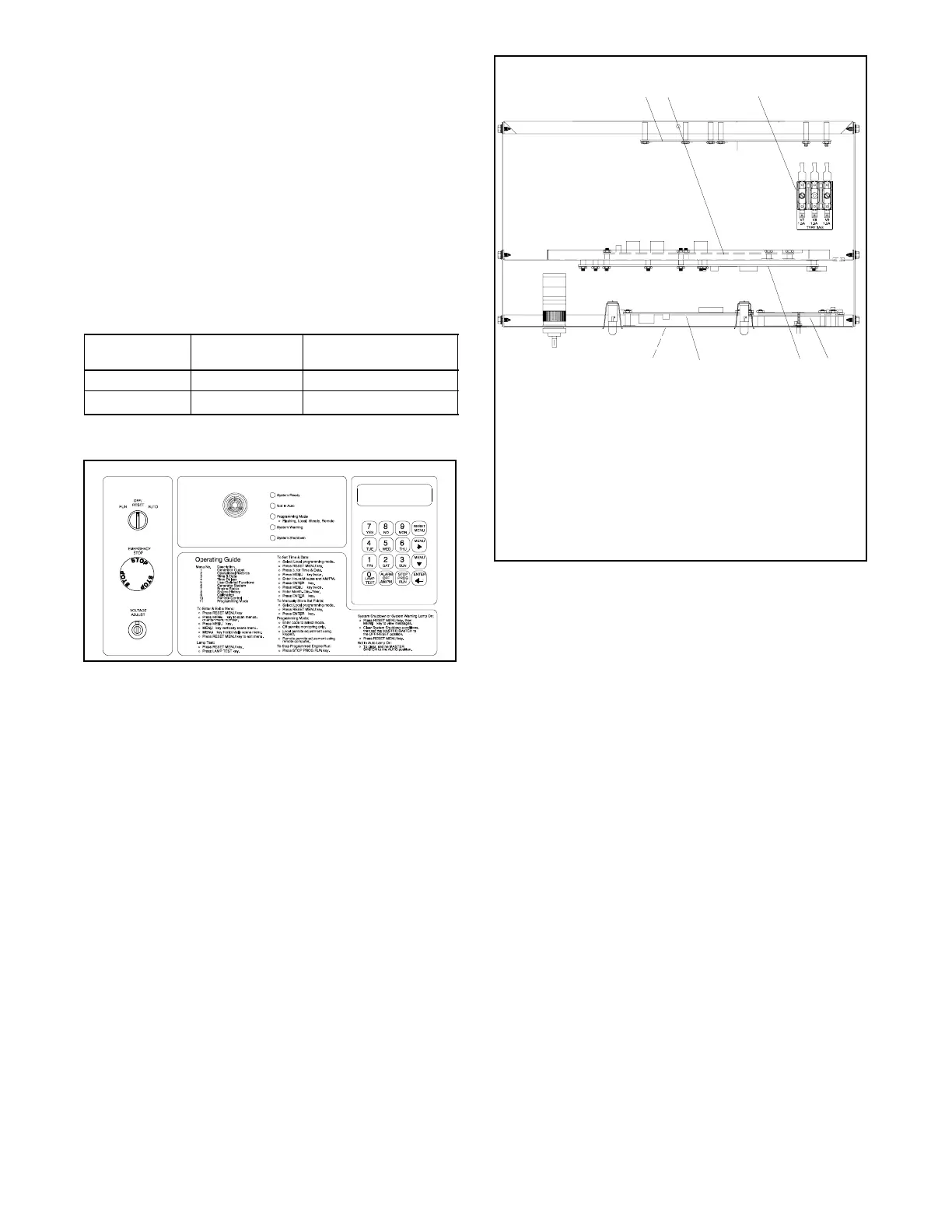
A-347946A-D
467
1. Interconnection circuit board
(TB1, TB2, TB3, and TB4 terminal strips)
2. Input conditioning circuit board
3. AC fuse block
4. Keypad and digital display circuit boards
5. Main logic (microprocessor) circuit board
with F1, F2, and F3 fuses
6. Indicator circuit board (LED and alarm horn)
7. Optional communication circuit board
(below indicator board)
3
5
12
Figure 4-4 Controller Circuit Boards and Fuses,
Controller Top View
4.2.3 Procedure
1. Acquire the display data from Menu 6, Generator
System.
When possible, make note of the data from the
existing controller for entry with the new circuit
board(s).
If the existing controller is not functional, the
installer must determine and document this
information for entry later in this procedure.
See Section 4.2.4, User-Defined Settings, for the
controller default settings.
a. Press the Reset Menu key on controller
keypad.
b. Go to Menu 6, Generator System and press the
down arrow key to System Voltage. See
Figure 4-5. Record all data from each display.

 Loading...


