TP-6356 4/12 63Section 4 Decision-Makerr 340 Controller
THREE PHASE DELTA →
WYE? NO
→
SINGLE PHASE? YES
GENERATOR SYSTEM
SYSTEM VOLTAGE
000
SYSTEM FREQUENCY
00
THREE PHASE WYE →
DELTA? NO
KW RATING
00
OVERVOLTAGE
00% 000V AC
UNDERVOLTAGE
00% 000V AC
OVERSPEED
00HZ 0000RPM
UNDERFREQUENCY
00% 00.0HZ
BA TTERY VOLTAGE (12 or 24)
LOW BATTERY VOLTAGE
00.0
HIGH BATTERY VOLTAGE
00.0
Menu 6
Figure 4-5 Menu 6, Generator System
2. Remove the generator set from service.
a. Place the generator set master switch in the
OFF position.
b. Disconnect the power to the battery charger, if
equipped.
c. Disconnect the generator set engine starting
battery(ies), negative (--) lead first.
3. Open the controller.
a. Remove the controller cover and hardware.
b. Partially disassemble the controller box.
Remove the two controller panel top screws
and center bottom screw and then loosen the
bottom screw on each side to swing the
controller panel down.
4. Remove the controller circuit board external
electrical connections.
Remove items mentioned in step a. input
conditioning circuit board A-351166 and/or b.
interconnection circuit board A-352160 as needed.
Note: Clearly mark all disconnected leads from the
Decision-Makerr 340 controller with tape to
simplify reconnection.
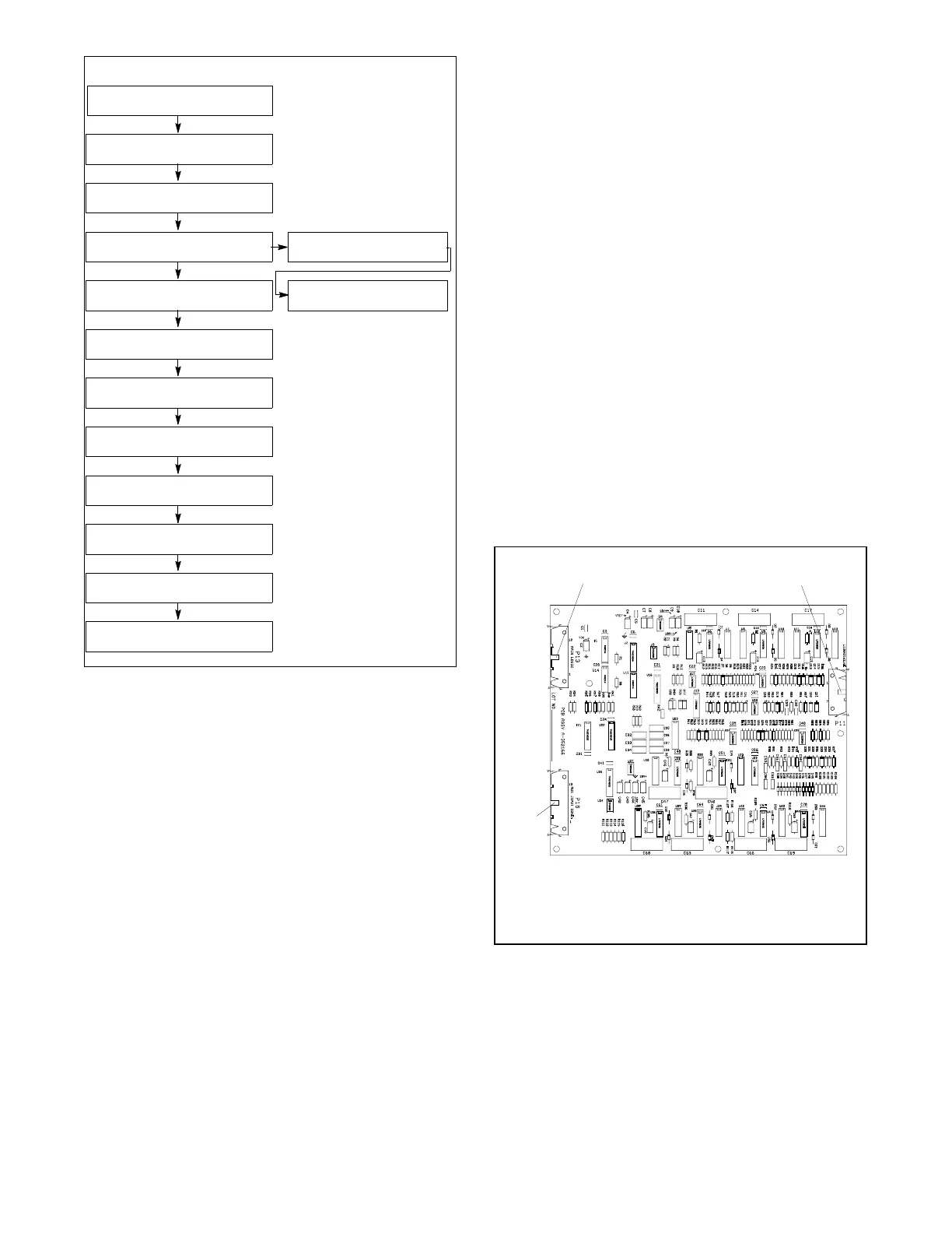
a. Input conditioning circuit board A-352166. See
Figure 4-6.
D P11 interconnection circuit board 14-pin
connector
D P13 main logic circuit board 24-pin
connector
D P18 input conditioning circuit board 26-pin
connector
A-352166-B
1. P13 main logic circuit board
2. P11 interconnection circuit board
3. P18 auxiliary input conditioning circuit board
12
3
Figure 4-6 Input Conditioning Circuit Board
A-352166

 Loading...


