TP-6356 4/1264 Section 4 Decision-Makerr 340 Controller
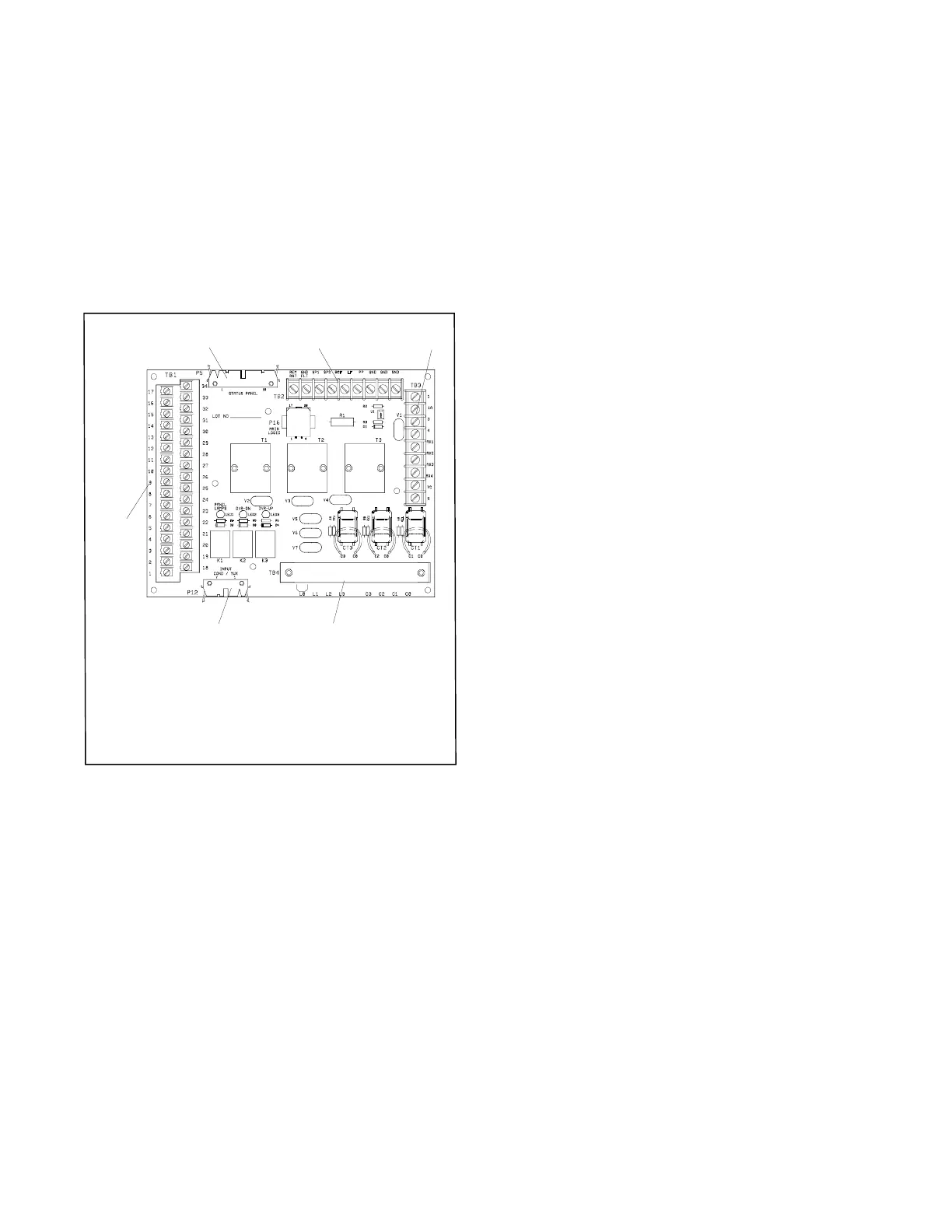
b. Interconnection circuit board A-352160. See
Figure 4-7.
D P5 status panel circuit board 30-pin
connector
D P12 input conditioning circuit board 14-pin
connector
D TB1 terminal strip connections
D TB2 terminal strip connections
D TB3 terminal strip connections
D TB4 terminal strip connections
1. P5 status panel circuit board
2. TB2 terminal strip connections
3. TB3 terminal strip connections
4. TB4 terminal strip connections
5. P12 input conditioning circuit board
6. TB1 terminal strip connections
A-352160-F
4
6
5
12 3
Figure 4-7 Interconnection Circuit Board A-352160
5. Remove/replace the circuit board(s) from the
controller.
a. Observe proper circuit board grounding
practices. See NOTICE in safety precautions
section.
b. Remove the mounting hardware.
c. Remove the defective circuit board(s).
d. Install the new circuit board(s) in the same
position as that of the old circuit board(s).
e. Secure the new circuit board(s) using the
existing hardware.
6. Attach the controller circuit board(s) external
electrical connections.
Reconnect the items mentioned in step a. input
conditioning circuit board A-351166 and/or b.
interconnection circuit board A-352160 as needed.
a. Input conditioning circuit board A-352166. See
Figure 4-6.
D P11 interconnection circuit board 14-pin
connector
D P13 main logic circuit board 24-pin
connector
D P18 input conditioning circuit board 26-pin
connector
b. Interconnection circuit board A-352160. See
Figure 4-7.
D P5 status panel circuit board 30-pin
connector
D P12 input conditioning circuit board 14-pin
connector
D TB1 terminal strip connections
D TB2 terminal strip connections
D TB3 terminal strip connections
D TB4 terminal strip connections
7. Assemble the controller.
a. Swing the front controller panel up and replace
and tighten the screws, as necessary.
b. Replace the controller cover and hardware.
Tighten all controller screws.
8. Restore power to the generator set.
a. Check that the generator set master switch is in
the OFF position.
b. Reconnect the generator set engine starting
battery, negative (--) lead last.
c. Reconnect power to the battery charger, if
equipped.

 Loading...


