182 Section 9 Gas Fuel Systems TP-6356 4/12
d. Connect an ignition timing light to the engine.
Follow the ignition timing light manufacturer’s
instructions.
Typically the ignition timing light connects to the
starting battery for power and the inductive
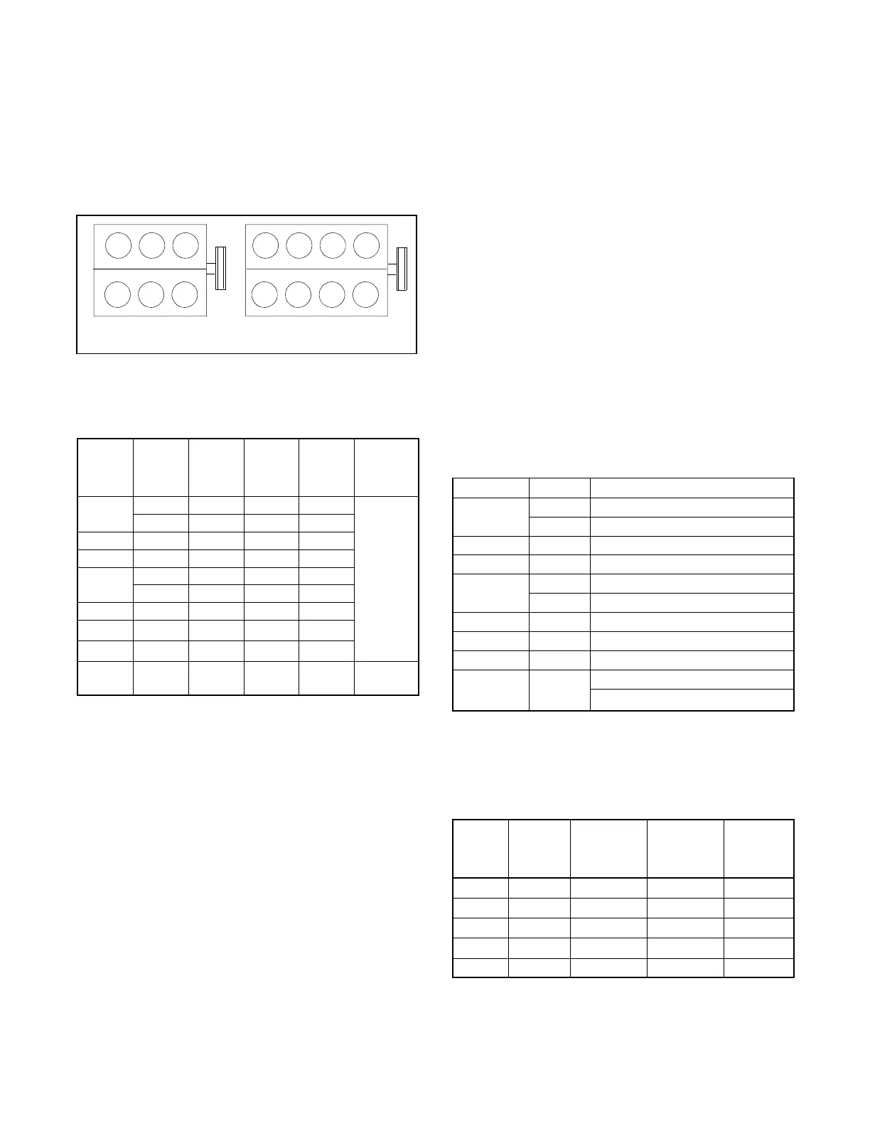
pickup goes on the no. 1 spark plug wire. The
no. 1 spark plug is in the front left side of the
engine. See Figure 9-41.
TT-1295
11
30--45 kW 50/60 kW
Figure 9-41 Engine No. 1 Cylinder/Spark Plug
e. Set the ignition timing light adjustment to the
value shown in Figure 9-42.
Model,
kW
Engine
NG
Timing
_BTDC
LP Gas
Timing
_BTDC
Dual
Fuel
Timing
_BTDC
Spark
Plug
Gap, mm
(in.)
30
4.3 L 32 28 32
0.89
(0.035)
3.0 L 0 0 0
35 4.3 L 32 28 32
45 4.3 L 32 28 32
50
5.7 L 36 28 32
5.0 L 36 28 32
60 5.7 L 36 28 32
80 8.1 L ECM ECM ECM
100 8.1 L ECM ECM ECM
125 8.1 L ECM ECM ECM
0.64
(0.025)
Figure 9-42 Engine Ignition Timing
f. Place the generator set master switch in the
RUN position to start the generator set.
g. Point the ignition timing light at the engine
timing plate mark and slowly turn the distributor
CW or CCW until the crankshaft pulley groove
aligns with the engine timing plate mark.
h. Place the generator set master switch in the
OFF position to stop the generator set.
i. Tighten the distributor hold-down clamp to
25 Nm (18 ft. lb.) being careful not to alter the
distributor position.
j. 30 kW model with the 3.0 L GM engine only.
Remove the lead from pin B lead at the battery
positive (+) terminal. Unplug GM39651 service
harness adapter from the distributor.
Reconnect the 4-pin harness connector to the
base of the distributor.
k. Disconnect the ignition timing light from engine.
8. Adjust the fuel mixture using Section 9.12.
9.12 Fuel Mixture Adjustment
(Oxygen Sensor Service Kit
GM29385 )
(30--125 kW GM-Powered Models with
Woodward and E-Controls Governor)
Adapted from Service Bulletin SB-634.
This section details fuel mixture adjustment for General
Motors engine-powered generator sets. Figure 9-43
lists specification numbers for generator sets including
engine models.
Model, kW Engine Spec No.
30
4.3 L GM22383-GA1, 7, 10, 13, 14
3.0 L GM22316-GA1, 4
35 4.3 L GM22383-GA2, 8, 11, 15, 16
45 4.3 L GM22383-GA3, 9, 12, 17, 18
50
5.7 L GM13686-GA1, 3, 5, 7
5.0 L GM21302-GA1, 5, 7
60 5.7 L GM21302-GA2, 6, 8
80 8.1 L GM22407-GA1,2,3,4
100 8.1 L GM22407-GA5,6,7,8
125 8.1 L
GM20568-GA1, 2
GM25339-GA1,2,3,4
Figure 9-43 Specification Numbers
Figure 9-44 provides the differences in engine
components and the optimum air/fuel mixture measured
with an oxygen sensor in volts.
Model,
kW
GM
Engine
Fuel Mixer
Type
Electronic
Control
Unit (ECU)
Type
Air/Fuel
Mixture
Measured
in V olts
30 3.0 Nolff E-Controls 2.50--2.65
30--45 4.3 Woodward PSI 2.35--2.45
50/60 5.0, 5.7 Woodward PSI 2.60--2.80
80/100 8.1 Nolff E-Controls 2.50--2.65
125 8.1 Turbo Nolff E-Controls 2.50--2.65
Figure 9-44 Engine Components and Optimum
Air/Fuel Mixture Values

 Loading...


