50 Disassembly and assembly SEN04132-01
PC130-8
23
q Step 7 – 9 is optional (for breaker specifi-
cation).
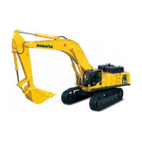
7. Disconnect the following PPC hoses from the
PPC valve. The
color of the band is;
q (7): Yellow
q (8): No color
a Plu
g the hose to stop oil flow-out.
8. Disconnect connectors P14 (9) and P15 (10).
9. Disconnect connectors V30 (11) and V13 (12).
10. Disconnect ground (13). From the left,
T04, T05, T06, T07, T09, T10
11. Disconnect clamp (14).
12. Disconnect connector A08 (15), (16) from the
cl
ip.
13. Disconnect hose (17).
a Ch
eck the connecting point.
a Plu
g the hose to stop oil flow-out.
a Disconn
ect the work equipment PPC hose
(P) at joint box side. (See procedure 30.)
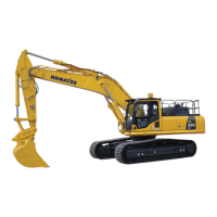
14. Disconnect connector P17 (18) from the air
co
nditioner tube.
15. Remove the clamp and disconnect spacer
(1
9).
16. Disconnect hose (20).
a Ch
eck the connecting point.
a Plu
g the hose to stop oil flow-out.
17. Disconnect heater hose (21).
a Ch
eck the connecting point.
18. Remove mounting bolt (22) and disconnect air
co
nditioner tube (23). [*1]
19. Remove clamps (24) and (25). [*2]
20. Disconnect clamp (26). (If equipped)
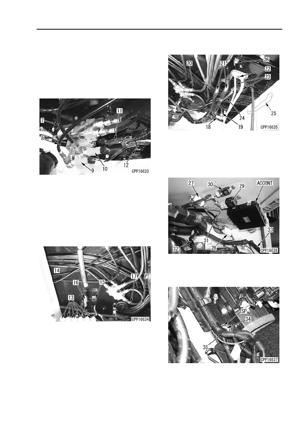
21. Disconnect connectors N10 (27) and AC01
(
28).
22. Disconnect connectors R20 (29) and R21 (30).
23. Cut tie-wrap (31) and draw in wiring harness
(
32).
24. Disconnect the clamp of wiring harness (33).
25. Remove grommet (34).
26. Move wiring harness (35) to the outside of the
floo
r frame.
a (SP)
is made of sponge.
 Loading...