Testing PPC valve output
pressure 1
a Testing tools for PPC valve output pressure
a Test PPC valve output pressure after confirm-
ing that control circuit original pressure is nor-
mal.
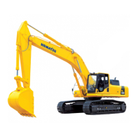
1. Remove PPC oil pressure switches (1) through
(8) in the hydraulic circuits to be tested. Con-
nector numbers are shown in brackets ( ).
a (1) (8) are installed to the PPC junction
block in the rear of the cab.
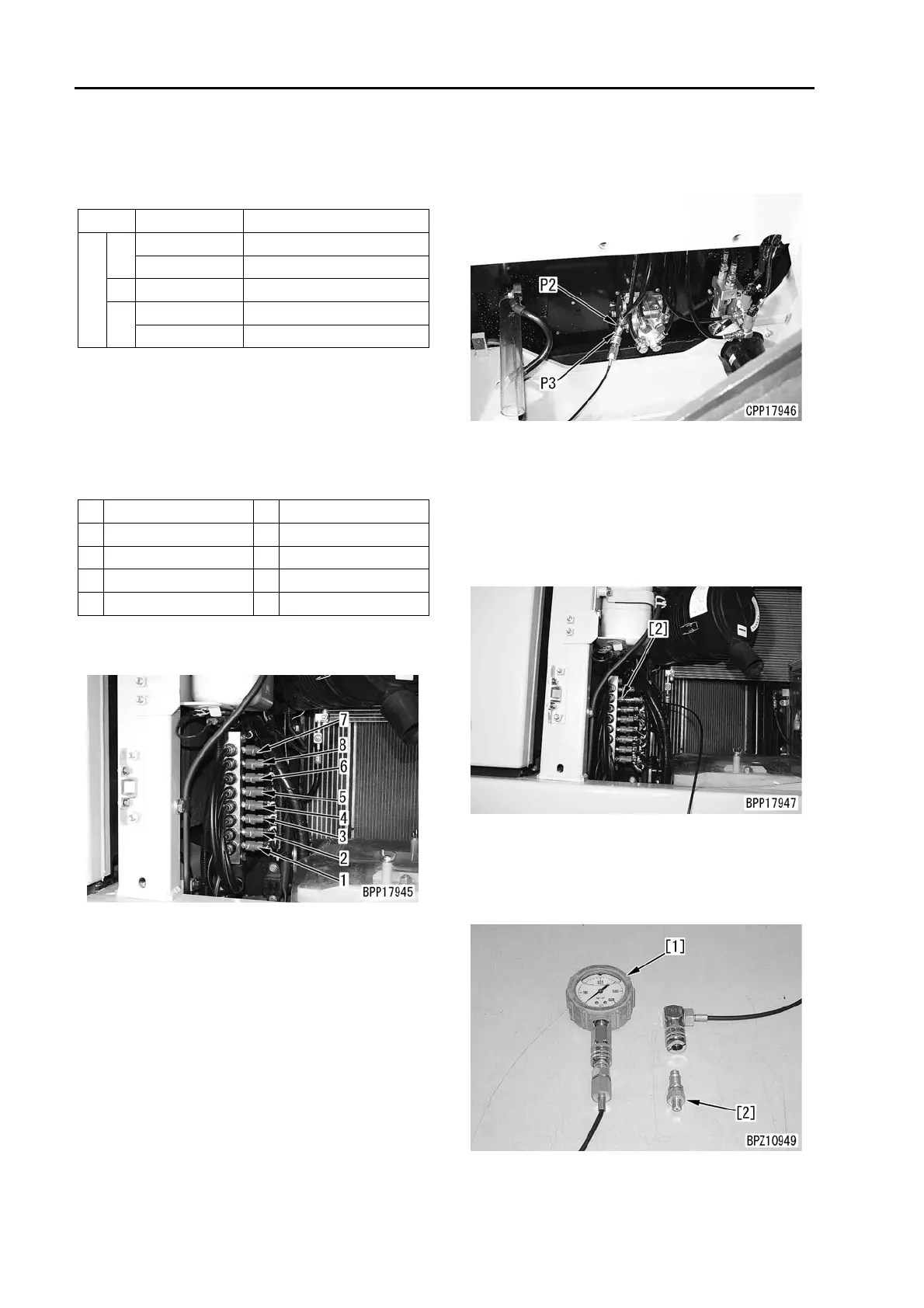
a Install nipple P3 to adapter P2 and mea-
sure the travel PPC pressure at the valve
box elbow.
2. Fit fitting [2] of hydraulic tester P1 and connect
oil pressure gauge [1].
a Use an oil pressure gauge with the capacity
of 5.9 MPa {60 kg/cm
2
}.
a The testing tools installed to the mounting
part of the boom RAISE PPC oil pressure
switch are shown in the figure.
3. Start the engine and keep it running until the
hydraulic oil temperature rises to the operating
range.
a Turn OFF the auto-decelerator switch.
Symbol Part No. Part name
P
1
799-101-5002 Hydraulic tester
790-261-1204 Digital hydraulic tester
2 799-401-3100 Adapter (Size: 02)
3
799-101-5220 Nipple (10 x 1.25 mm)
07002-11023 O-ring
No. Circuit to be tested No. Circuit to be tested
1 Boom, RAISE (P06) 5 Bucket, CURL (P01)
2 Boom, LOWER (P02) 6 Bucket, DUMP (P05)
3 Arm, IN (P04) 7 Swing, left (P07)
4 Arm, OUT (P08) 8 Swing, right (P03)
 Loading...