SEN03766-02 00 Index and foreword
20
PC130-8
Handling of connectors newly used for engines 1
a Mainly, following engines are object for follow-
ing connectors.
q
95E-5
q
107E-1
q
114E-3
q
125E-5
q
140E-5
q
170E-5
q
12V140E-3
1. Slide lock type
(FRAMAT
OME-3, FRAMATOME-2)
q
95 – 170, 12V140 engines
q
Various pressure sensors and NE
speed sensor
Examples)
Intake air pressure sensor in intake
manifold: PIM
(125, 170, 12V140 engines)
Oil pressure sensor: POIL
(125, 170, 12V140 engines)
Oil pressure switch
(95, 107, 114 engines)
Ne speed sensor of flywheel housing:
NE
(
95 – 170, 12V140 engines)
Ambient pressure sensor: PAMB
(125, 170, 12V140 engines)
Disconnect connector (1) according to the fol-
lowing procedure.
1) Slide lock (L1) to the right.
2) While pressing lock (L2), pull out connec-
tor (1) toward you.
a E
ven if lock (L2) is pressed, connec-
t
or (1) cannot be pulled out toward
you, if
part A does not float. In this
case, float part A with a small screw-
driver while press lock (L2), and then
p
ull
out connector (1) toward you.
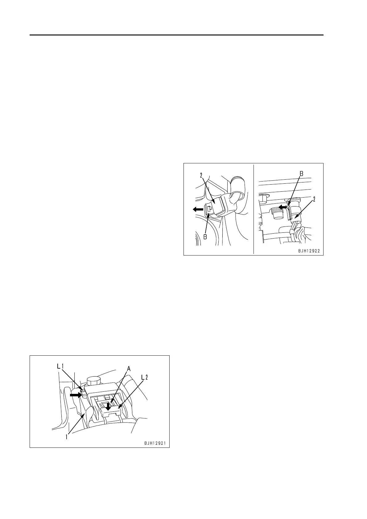
2. Pull lock type (PACKARD-2)
q
95 – 170, 12V140 engines
q
Various temperature sensors
Example)
Intake air temperature sensor in
int
ake manifold: TIM
Fuel temperature sensor: TFUEL
Oil temperature sensor: TOIL
Coolant temperature sensor: TWTR,
et
c.
D
isconnect the connector by pulling lock
(B
) (on the wiring harness side) of connec-
tor (2) outward.
 Loading...