SEN03773-00 10 Structure, function and maintenance standard
2 PC130-8
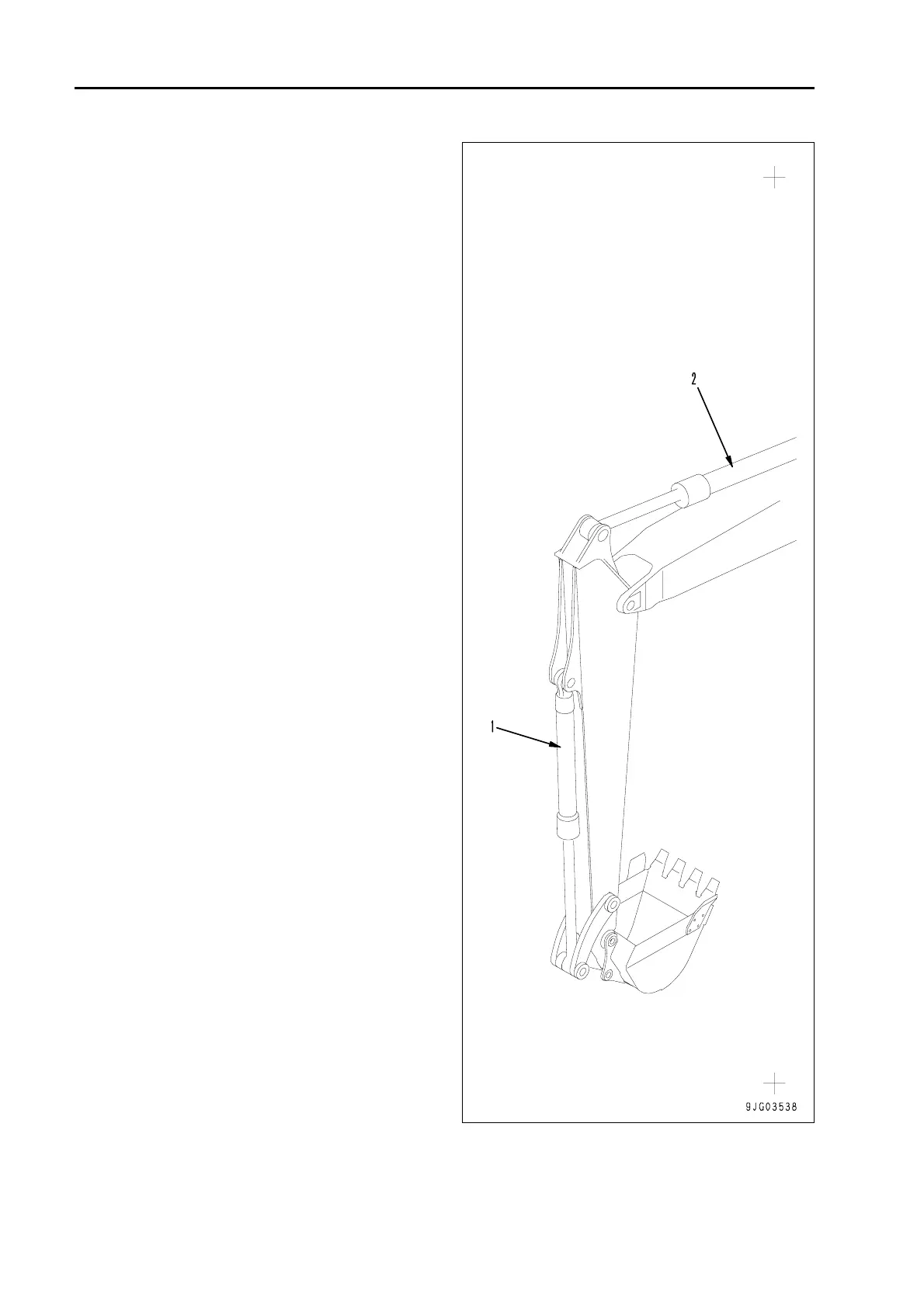
Hydraulic equipment layout
drawing 1
1. Bucket cylinder
2. Arm cylinder
3. Control valve
4. Solenoid valve
5. Accumulator (for PPC circuit)
6. Boom cylinder
7. Hydraulic tank
8. Swing motor
9. Hydraulic pump
10. R.H. travel motor (R.H. Final drive)
11. Oil cooler
12. L.H. travel motor (L.H. Final drive)
13. L.H. work equipment PPC valve
14. R.H. work equipment PPC valve
15. Center swivel joint
16. Travel PPC valve
17. Attachment PPC valve
(Machine ready for attachment)
 Loading...