SEN04127-02 50 Disassembly and assembly
4 PC130-8
Installation
q Carry out the installation in the reverse order of
removal.
[*1]
a Set the boot slit facing outward and downward.
a The boot is designed with fire safety to prevent
fuel from splashing onto the hot engine if fuel
leaks.
[*2]
k Never bend a high-pressure pipe for the
convenience sake.
k The clamp used for fixing a high-pressure
pipe must be a genuine Komatsu part and it
must be tightened to the specified torque.
k Be sure to install the boot to the sleeve nut
after installing the high-pressure pipe.
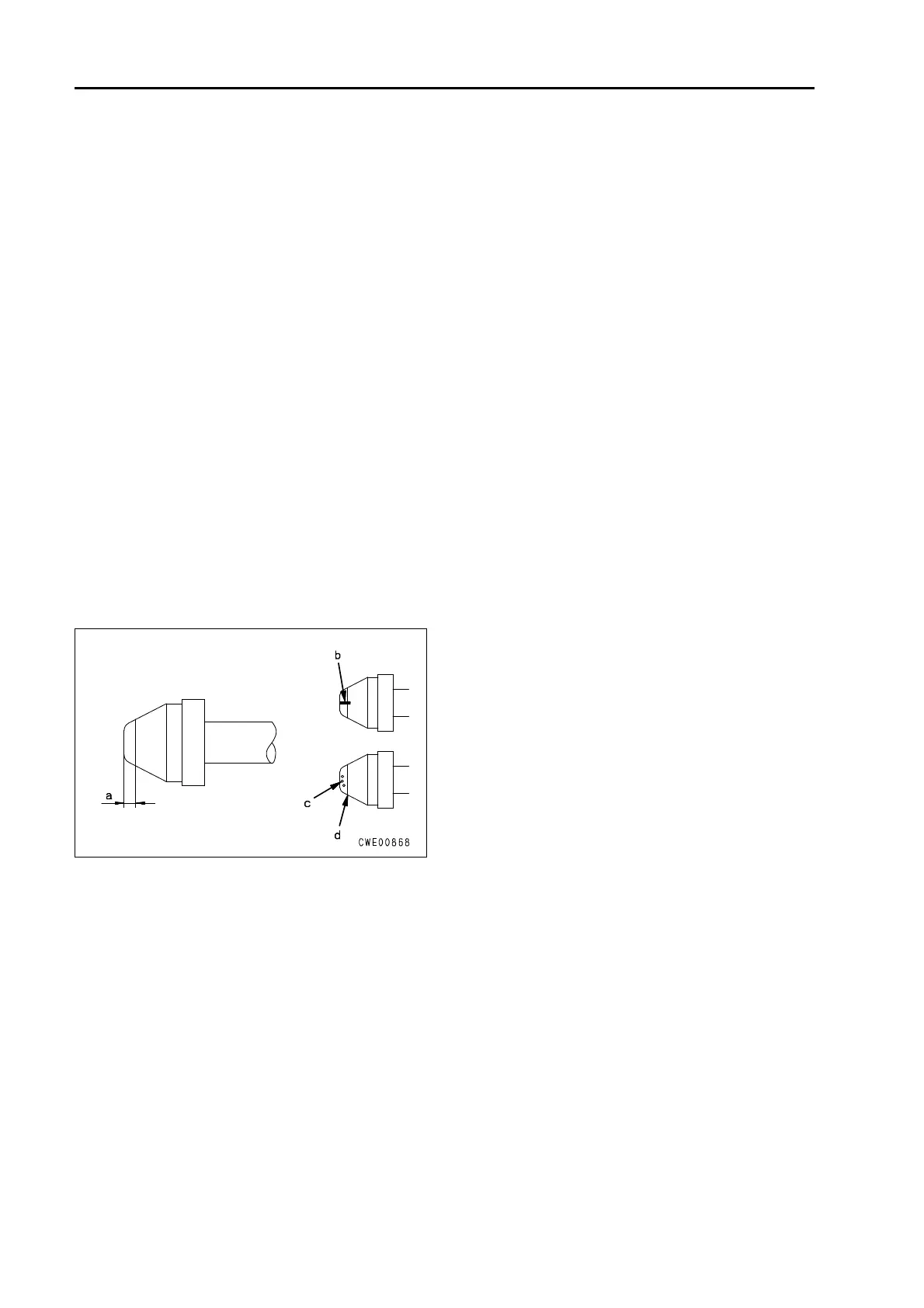
a Before installing a high-pressure pipe, confirm
the following points. If any abnormality was
found, replace it with new one. Otherwise,
leakage of fuel can result.
q No visible striations (b) or patchy dents (c) in
the taper seal portion of the connection ( (a)
portion: area 2 mm inside the tip).
q No deformation in portion (d) (at the end of the
taper seal portion: 2 mm inside the tip).
3 Sleeve nut (10) on the common rail side:
25.5 – 29.4 Nm {2.6 – 3.0 kgm}
3 Sleeve nut (11) on the supply pump side:
18 – 23 Nm {1.9 – 2.3 kgm}
[*3]
3 Joint bolts (14) and (15):
24.5 – 34.3 Nm {2.5 – 3.51 kgm}
3 Joint bolt (16):
19.6 – 29.4 Nm {2.0 – 3.0 kgm}
[*4]
a For mounting bolt (20), install M6 bolt with LT-
2A.
[*5]
3 Pump gear mount nut:
65 – 75 Nm {6.6 – 7.6 kgm}
 Loading...