50 Disassembly and assembly SEN04130-01
PC130-8
31
Assembly
Only the precautions for assembling the travel PPC
valve assembly are discribed.
a When
assembling, clean and inspect the parts
closely and take care fully so that dirt, rust,
flaw, etc. will not cause a trouble.
a When inst
alling piston (7), apply grease (G2-
LI) to its outside and the inside of the body
hole.
a In
stall spring (4) with its small diameter side on
the shim (3) side.
q Diameter of spring (Inside diameter)
Small diameter side: 4.9, Large diameter
side
: 5.55
a Assem
ble shaft (16) with the following proce-
dure.
1) Using tool T2,
install bushing (14) to case.
a In
stall bushing from 10° chamfered
side.
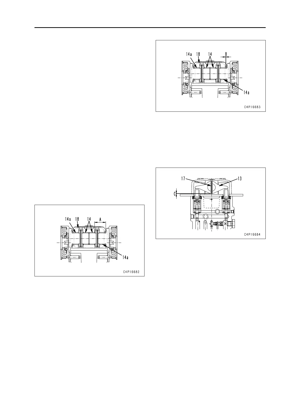
a Inst
alling dimension (A) of the bush-
ing should be as follows.
q A: 20.4 ± 0.3 mm
a Do no
t apply shock load to the bush-
ing directly.
2) Using tool T3, install bushing (14 a ) t o
case.
a In
stall bushing from 10° chamfered
side.
a Inst
alling dimension (B) of the bush-
ing (14a) should be as follows. (End
surface of bushing will tightly fit to the
end surface of case.)
q B: 0 mm
a Do no
t apply shock load to the bush-
ing directly.
3) Install lever (13).
4) Install shaft (16).
5) Using tool T4, insatll pin
(17).
a In
stalling dimension (C) of the pin
(17) should be as follows.
q C: 0 – 0.5 mm
a Do
not apply shock load to the pin
directly.
a Apply grease (G2-LI) to the rocking part of
shaft (16) and the contact surfaces of lever
(13) and piston (7) and the contact surfaces of
damper (21) and pin (20).
2 Quantity of grease (G2-LI)
Rocking part of shaft:
4 – 8 cc/periphery
Contact surfaces of lever and piston:
0.3 – 0.8 cc/place
Contact surfaces of plate and pin:
0.3 – 0.8 cc/place
a Install washer (12) 1.6 mm thick first. If the dif-
ference between both sides at the stroke end
of the lever exceeds 0.7°, change the washer
thickness to reduce the difference to below 0.7
°. (If the washer thickness is reduced by 0.3
mm, the stroke end angle is increased by 0.39
°.)
q Thickness of washer t: 1.0, 1.3, 1.6
 Loading...