SEN04130-01 50 Disassembly and assembly
36 PC130-8
3) Remaining oil amount on the head side is
low.
4) Turn the starting switch to OFF position.
5) Turn the starting switch to ON position.
Set the work equipment lock lever in FREE
p
osition, and operate the R.H. and L.H.
work equipment control levers forward and
backward, and to the right and left.
a Th
e work equipment can be operated
with the battery charged in the PPC
accumulator, but the battery charged
in it will be discharged after the work
equipment control lever is operated a
couple of times.
6) Start the engine, run it with the fuel control
dial in
MIN (low idle) position for more
than 10 seconds so that the PPC accumu-
lator is accumulated.
7) Repeat the steps 4. to 6. to release the
remainin
g pressure in the hydraulic cylin-
der circuit.
8) Set the work equipment lock
lever in
LOCK position.
9) Loosen the oil filler cap of the hydraulic
t
ank slowly, and bleed the air in the
hydraulic tank.
k Leave the oil filler cap of the
hydraulic tank removed.
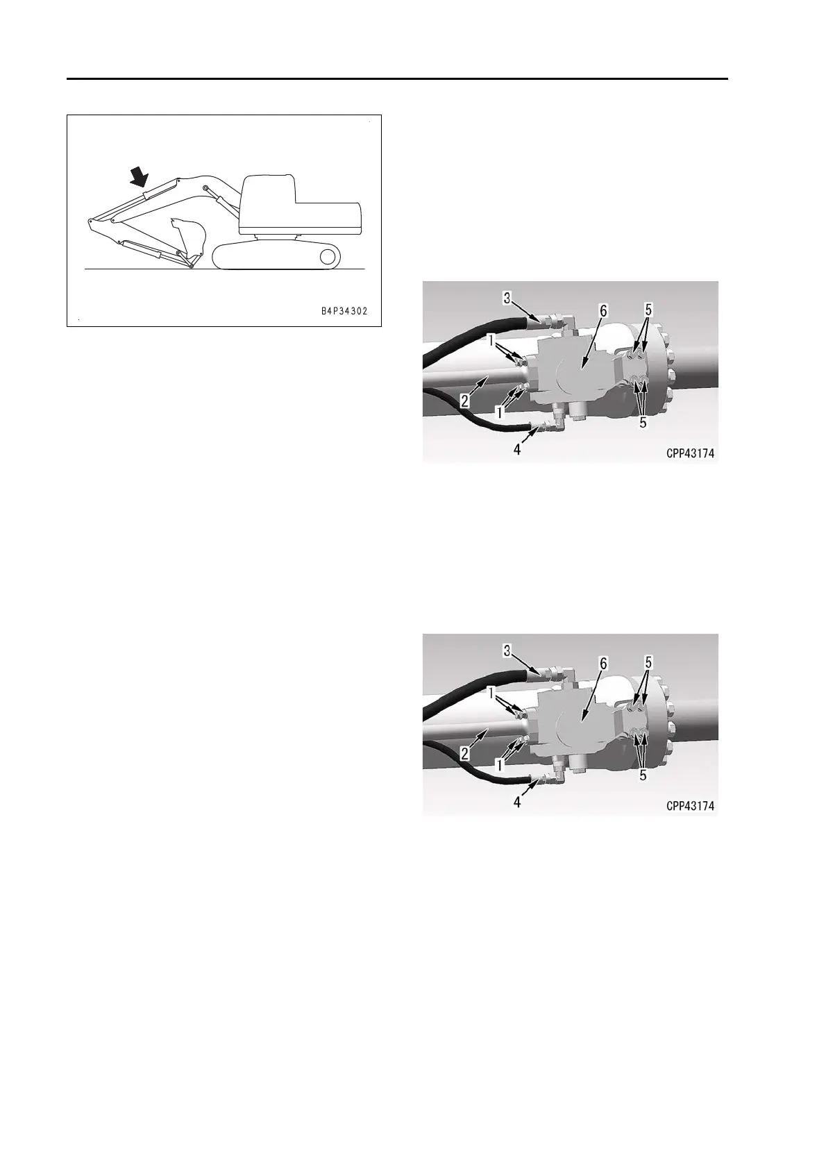
3. Anti-drop valve assembly
1) Place an oil container under the anti-drop
valve as
sembly (6) to receive oil.
k Place an oil mat as well in case the
oil leaks.
2) Disconnect the hoses (3) and (4).
k Slowly loosen the fitting of the
hose so that the remaining pres-
sure in the circuit between the anti-
drop valve and the cylinder is
released.
The remaining pressure may dam-
age the O-ring, and the oil may be
splashed. Use a waste cloth to pro-
tect the fitting and around it.
3) Slowly loosen the bolt (5) (4 pieces), and
c
heck that the oil pressure is released.
k Slowly loosen the bolt (5) in case
the inside pressure may be
remained.
4) Remove the bolts (1) (4 pieces), and dis-
connect the tube (2).
5) Remove the bolts (5) (4 pieces), and
re
move the anti-drop valve assembly (6).
Installation
1. Anti-drop valve assembly
1) Install the anti-drop valve assembly (6)
wit
h the bolts (5) (4 pieces).
2) Connect the tube (2) with the bolts (1) (4
p
ieces).
3) Connect the hoses (3) and (4).
2. Refilling with oil
a Refill
with oil to the specified level through
the oil filler port of the hydraulic tank. Start
the engine to circulate the oil through the
piping. Then check the oil level again.
3. Air bleeding
a Bleed
air from the hydraulic circuit. See
TESTING AND ADJUSTING, “BLEED
AIR FROM HYDRAULIC CIRCUIT”.
 Loading...