10 Structure, function and maintenance standard SEN03773-00
PC130-8
7
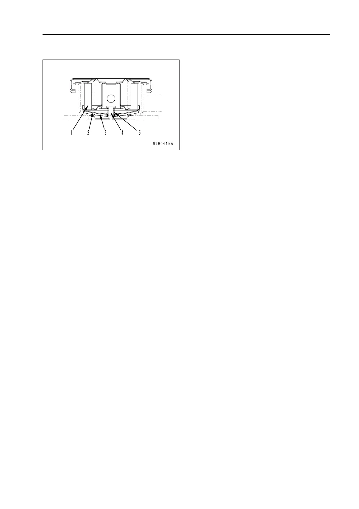
Breather
1. Filter element
2. Bottom plate
3. Gasket
4. Seam valve
5. Spring
Prevention of negative pressure in tank
q The hydraulic tank is enclosed and pressur-
ized. When the oil level in the hydraulic tank
drops, negative pressure is generated in the
tank.
To prevent this negative pressure generation,
seam valve (4) is opened to draw the atmo-
sphere to the tank.
(Intake valve set pressure:
0 – 0.49 kPa {0 – 0.005 kg/cm²})
Prevention of pressure rise in tank
q When the hydraulic circuit is operating, the
pressure in the hydraulic tank increases as the
hydraulic cylinder operates and the oil level
and temperature increase in the tank.
If the pressure in the tank rises above the set
value, bottom plate (2) is pushed up to release
the pressure in the tank.
(Exhaust valve set pressure:
16.7 ± 6.86 kPa {0.17 ± 0.07 kg/cm²})
 Loading...