B4-6 Fuel Tank B04026
FUEL TANK BREATHER VALVE
NOTE: The relief pressure of the fuel tank breather
valve is 70 - 89 kPa (10 - 13 psi).
Disassembly
1. Remove clamp (3, Figure 4-2), cover (2) and
screen (1).
2. Remove ball cage (10), solid ball (11) and float
balls (12).
3. Unscrew end fitting (7) from body (4).
4. Remove stem (8) and valve spring (5).
Assembly
1. Clean and inspect all parts. If any parts are
damaged, replace the entire assembly.
2. Place valve spring (5) into position in body (4).
3. Insert stem (8) into end fitting (7).
4. Screw end fitting (7) into body (4). Ensure the
components are properly aligned and seated.
5. Place screen (1) and cover (2) into position on
the breather. Install clamp (3).
6. Insert the balls into ball cage (10) with solid ball
(11) on top.
7. Insert the ball cage onto the stem. A minimum
of two cage coils must be seated in the groove
on the stem. Ensure the solid ball is able to seat
properly on the stem. If not, adjust the cage
accordingly.
FUEL RECEIVERS (WIGGINS QUICK FILL)
Fuel receiver assembly (2, Figure 4-1) is mounted on
the side of the fuel tank.
Keep the cap on the fuel receiver to prevent dirt build
up in valve area and nozzle grooves.
If fuel spills from the fuel tank breather valve (7), or if
the tank does not completely fill, check the breather
valve to see whether the float balls are in place and
the outlet screen is clean. If the breather valve is
operating properly, the problem will most likely be in
the fuel supply system.
LOW FUEL SWITCH
Low fuel switch (13, Figure 4-1) controls the low fuel
level indicator on the overhead warning indicator light
panel in the operator cab. The switch is calibrated to
turn on the low fuel indicator when the usable fuel
remaining in the tank is approximately 25 gallons (95
liters).
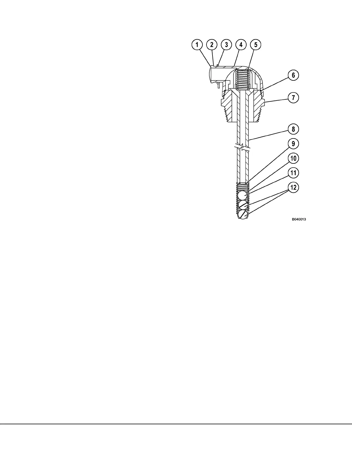
FIGURE 4-2. BREATHER VALVE
1. Screen
2. Cover
3. Clamp
4. Body
5. Valve Spring
6. O-Ring
7. End Fitting
8. Stem
9. O-Ring
10. Ball Cage
11. Solid Ball
12. Float Ball

 Loading...


