L07034 Hoist Circuit L7-3
HOIST CIRCUIT
HOIST CIRCUIT OPERATION
The following hoist circuit operation description
describes the basic hoist circuit. Details of individual
component operation is outlined under the individual
component descriptions.
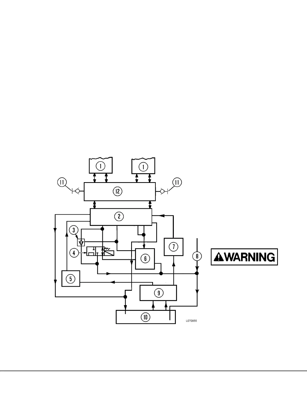
Hydraulic fluid is supplied by a tank (10, Figure 7-1)
located on the left frame rail. Hydraulic oil is routed to
a tandem gear type pump (9), driven by a driveshaft
on the traction alternator.
Pump output is directed to two, high pressure filters
(5 & 7) mounted on the side of the fuel tank. Hydrau-
lic oil from the filters is directed to the hoist valve (2),
mounted on a modular assembly containing the hoist
pump, steering/brake pump, hoist valve and counter-
balance valve manifold.
The hoist valve directs oil to the body hoist cylinders
(1) for raising and lowering the dump body. Hoist
valve functions are controlled by the operator
through a flexible cable to the hoist pilot valve (6) in
the hydraulic component cabinet located behind the
operator's cab. Also in the hydraulic cabinet is the
hoist-up limit solenoid (4). The hoist-up limit solenoid
prevents the hoist cylinders from extending to maxi-
mum physical limit. A counterbalance valve in the
overcenter manifold (12) prevents abrupt cylinder
extension due to material buildup on the tail of the
body.
Quick disconnect fittings (11) allow the use of
another truck’s hydraulic system to dump a load in
the body if the hoist pump, hoist valve or related
components are inoperable.
FIGURE 7-1. HOIST CIRCUIT SCHEMATIC
1. Hoist Cylinders
2. Hoist valve
3. Pilot Operated Check Valve
4. Hoist Up Limit Solenoid
5. Filter
6. Hoist pilot valve
7. Filter
8. Return from Flow Amplifier valve
9. Hoist Pump
10. Hydraulic Tank
11. Quick Disconnects
12. Counterbalance Valve Manifold
Hydraulic hoses deteriorate with age
and use. Prevent possible malfunc-
tions by inspecting all hoses periodi-
cally. Replace any hose showing
wear, damage, or deterioration.

 Loading...


