J5-4 Rockwell Wheel Speed Front Disc Brakes 10/06 J05024
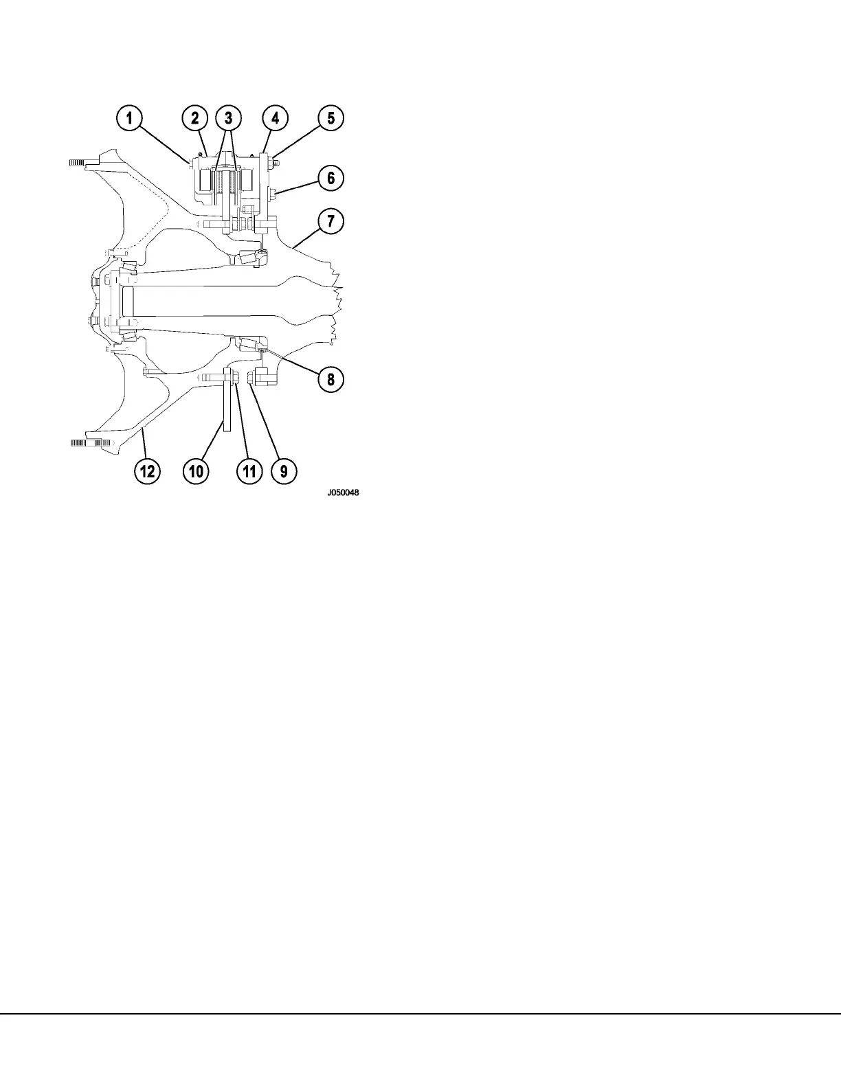
6. Remove nuts and flatwashers (5, Figure 5-2)
and remove outboard half of brake caliper.
Remove cap screws and flatwashers (6) secur-
ing inboard half of caliper to the brake adapter
(4). Remove Inboard caliper.
NOTE: It may be necessary to pry between the brake
lining and disc in order to force the piston inward to
permit inboard caliper removal.
7. Move the brake caliper assemblies to a clean
work area for rebuild.
Installation
Prior to brake caliper installation, refer to Brake Lin-
ing for wear limits regarding brake linings and brake
discs. If linings and/or disc is worn beyond accept-
able limits, replace the parts at this time.
1. After repair, cleaning and inspection of the
brake caliper, install each brake component to
its original location.
2. Install the inboard half of caliper assembly (2,
Figure 5-2) to the top leg of the brake caliper
support and secure caliper assembly with four
cap screws (6). Tighten cap screws to standard
torque.
3. Repeat Step 2. at the other two brake caliper
support legs.
4. Install the upper outboard half of brake caliper
assembly (2) to the top leg of the brake caliper
adapter (4) and secure with six cap screws,
washers and nuts (1 & 5). The pistons in both
caliper assemblies will collapse against the
brake disc. Tighten cap screws to standard
torque.
5. Install crossover tubes (2, 4 & 7, Figure 5-1).
Tighten crossover tube connections securely.
6. Install the three brake line hoses at each “T”
connection (3, 5 & 6).
7. Refer to Brake Bleeding Procedures in this Sec-
tion and bleed air from caliper assemblies.
1. Cap Screw/Flat-
washer
2. Brake Caliper
3. Lining
4. Brake Adapter
5. Nut & Flatwasher
6. Cap Screw/Flat-
washer
7. Spindle
8. Oil Drain
9. Cap Screw/Flat-
washer
FIGURE 5-2. DISC AND CALIPER ASSEMBLY

 Loading...


