E3-16 AC Drive System Electrical Checkout Procedure 10/06 E03018
(Version 21 Software)
PSC Digital Output Checks
1. Open circuit breakers 1 and 2 for gate driver
power converters 1 and 2.
2. Connect the serial communication cable from the
PTU to the PSC port (DIAG1) on the DID panel
located on the back wall of the operator cab.
3. Make sure that the directional control lever is in
PARK and the rest switch is in the REST position.
4. Turn control power switch (1, Figure 3-1) and the
key switch ON.
To check the PSC digital outputs:
Click START > Programs > GEOHVPTU_2.0 >
AC TOOLS > wPTU AC v21.01
Select “Normal” mode {enter}
Type password “ok75e” {enter}
Click “LOGIN to wPTU Toolbox”.
Under “Engine Stopped Task”, double-click
“PSC Manual Test”.
The “PSC Manual Test” screen looks similar to
the “PSC Real Time Data” screen in Figure 3-3.
Clicking the buttons in the “Digital Outputs” field
will toggle the output on and off. See Table III.
NOTE: For Steps 1 through 5, remove the contactor arc
chutes and observe the contacts while they are closed
to ensure that the tips are mating properly. These
contactors are interlocked so they will not close with
the arc chutes removed. For testing, the interlock can
be pushed inward to allow contact closure with the arc
chute removed.
NOTE: Do not check CMCTL at this time.
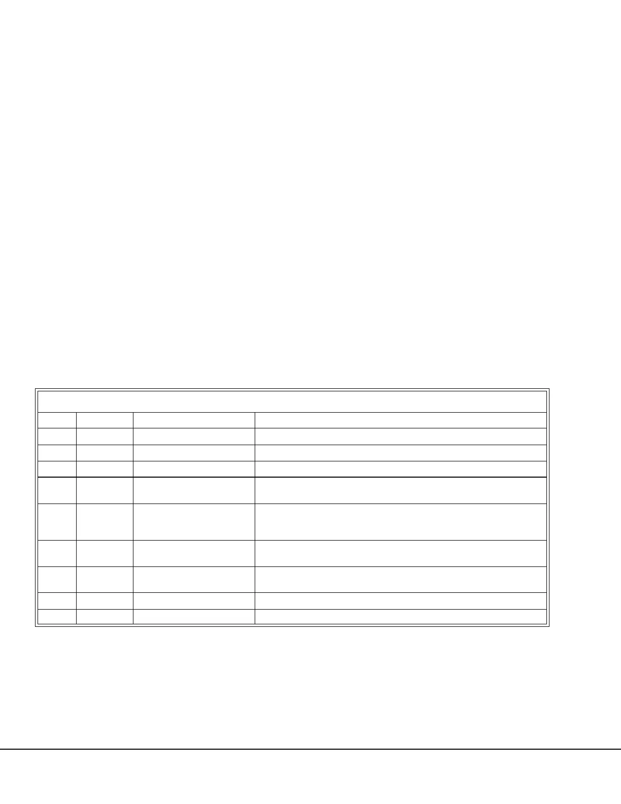
TABLE III. PSC DIGITAL OUTPUT CHECKS
STEP OUTPUT DESCRIPTION DEVICE CHECKOUT
1 RP1 RP1 Contactor Verify that RP1 picks up and RP1FB is highlighted.
2 RP2 RP2 Contactor Verify that RP2 picks up and RP2FB is highlighted.
3 RP3 RP3 Contactor (If installed) If installed, verify that RP3 picks up and RP3FB is highlighted.
4 GFR GFR Contactor Verify that the GFR relay picks up.
5 GF GF Contactor
Verify that the GF contactor picks up and GFFB is highlighted on the PTU. The
GF Cutout Switch must be in the NORMAL (up) position to check.
6 GF GF Cutout Switch Safety Check
Move the GF Cutout Switch to the CUTOUT (down) position. Verify that the GF
contactor does not pick up and GFFB is not highlighted on the PTU. Return the
GF Cutout Switch tothe NORMAL (up) position.
7 CPRL Control Power Relay
With CPRL highlighted, turn off the Control Power Switch and verify that control
power is not lost. Turn the switch back on.
8 AFSE Alternator Field Static Exciter
With AFSE highlighted, verify 24 volts to ground on the “+25” terminal on the
AFSE terminal board.
9 FORT Forward Travel Direction Verify that circuit 72FD changes from 24VDC to 0VDC when FORT is activated.
10 REVT Reverse Travel Direction Verify that circuit 79RD changes from 24VDC to 0VDC when REVT is activated.

 Loading...


