C04034 Power Train C4-9
Service
Complete instructions covering the disassembly,
assembly and maintenance of the engine and its
components can be found in the engine manufac-
turer's service manual.
Installation
1. Align engine to subframe and install front
mounting cap screws and lockwashers (5, Fig-
ure 4-7). Align and install rear engine mounting
cap screws and lockwashers (2) through cradle
structure, but do not tighten at this time. Tighten
front mount cap screws to 465 N·m (345 ft lbs)
torque.
2. Install alternator on engine following instruc-
tions for “Engine/Alternator Mating”.
3. Tighten rear engine mounting cap screws (2) to
465 N·m (345 ft lbs) torque after alternator is
installed.
4. Adjust setscrew (3, Figure 4-1) to equalize gap
(5) between cradle structure (1) and subframe
(4) at left and right side. Lock setscrew with jam
nut (2).
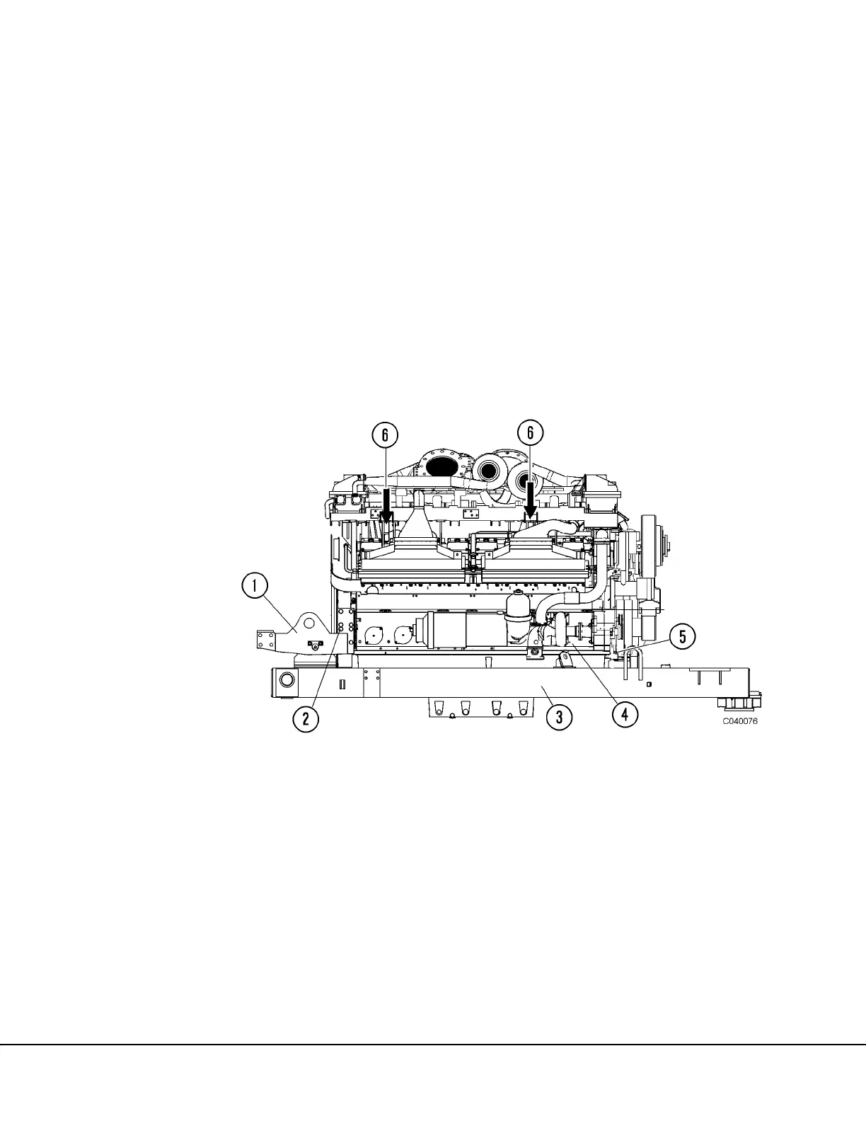
FIGURE 4-8. ENGINE MOUNTING
1. Cradle Structure
2. Cap Screws and Lockwashers
3. Engine Module Subframe
4. Engine
5. Cap Screws and Lockwashers
6. Engine Lift Points

 Loading...


