E3-8 AC Drive System Electrical Checkout Procedure 10/06 E03018
(Version 21 Software)
Battery and Control Circuit Checks -
Battery Power ON
Make sure that the link voltage is drained down
before servicing the propulsion system or
performing tests.
1. Prepare for the following checks by performing
the following procedure:
a. Remove the 50 amp fuse (BATFU) from the left
wall of the right side compartment of the
control cabinet.
b. Disconnect circuit wire 21B from the starter
solenoid.
c. Plug in all the cards in the ICP panel. Verify
that all the CN connectors are connected and
control power switch (1, Figure 3-1) is OFF.
d. Verify that all circuit breakers are closed and
the battery disconnect switches are
deactivated.
e. Make sure that the key switch and the 5 minute
delay timer are OFF.
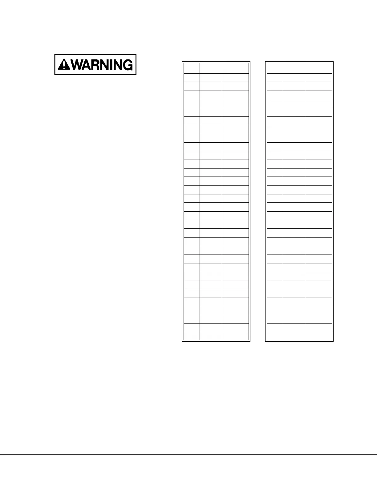
Power Supply Check (PS):
2. Remove the CN1 connector on the power supply.
Use an ohmmeter to check the harness side
connector pins to ground. Refer to Table II for the
resistance value at each pin.
3. Check for 1.4K ohms between TB3-K and TB3-L
(LEM +24V to -24V power supply busses).
4. After resistance checks are complete, reconnect
CN1 connector.
TABLE II. POWER SUPPLY HARNESS
RESISTANCE CHECKS
Pin Ohms Circuit Pin Ohms Circuit
127+5 320return
227+5 330return
327+5 340return
427+5 350return
527+5 360return
627+5 370return
7—— 381K-15
8 12K +5 39 1K -15
9 12K +5 40 1K -15
10 12K +5 41 1K -15
11 27 +5 42 0 return
12 0 return 43 — —
13 0 return 44 0 return
14 0 return 45 0 return
15 0 return 46 860 +24
16 0 return 47 50 BP24
17 0 return 48 860 +24
18 — — 49 — —
19 0 return 50 — —
20 0 return 51 — —
21 0 return 52 — —
22 — — 53 — —
23 770 +15 54 0 return
24 770 +15 55 0 return
25 770 +15 56 1.4K -24
26 770 +15 57 8K psstat
27 — — 58 1.4K -24
28 210 +15 59 — —
29 210 +15 60 — —
30 0 return 61 — —
31 0 return 62 — —

 Loading...


