COMPONENT MAINTENANCE MANUAL
AVIATION PRODUCTS
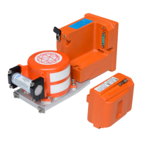
Model FA5000
Assembly
23–70–30
Use or disclosure of information on this sheet is subject to
the restrictions on the cover page of this document.
Rev. 02 Page 702
July 21/17
A. General Assembly Techniques
The Model FA5000 circuit board components are mounted using Surface Mount
Technology (SMT) and also incorporate extensive software programming to function-
ally configure the logic circuits. Thus, Level-3 repair of these circuit boards requires
specialized factory equipment, diagnostic software, training, and techniques; there-
fore, such boards are not field-repairable while the unit is under warranty. Conse-
quently, in accordance with the accepted Level-2 repair philosophy for the FA5000
CVR, a known defective circuit board assembly shall be returned to the factory for
repair or replacement.
NOTE
: Numbers shown in parentheses in the following text are the
Illustrated Parts List (IPL) figure number followed by the IPL
item number for a particular part; e.g., (1-115) for IPL Figure 1,
Item 115. For items listed in the parts list but not illustrated, the
item number is preceded by a “-”.
The Assembly procedures begin with the Main Processor PWA installation then con-
tinue with the Aircraft Interface PWA installation, CSMU installation, and Underwater
Acoustic Beacon installation.
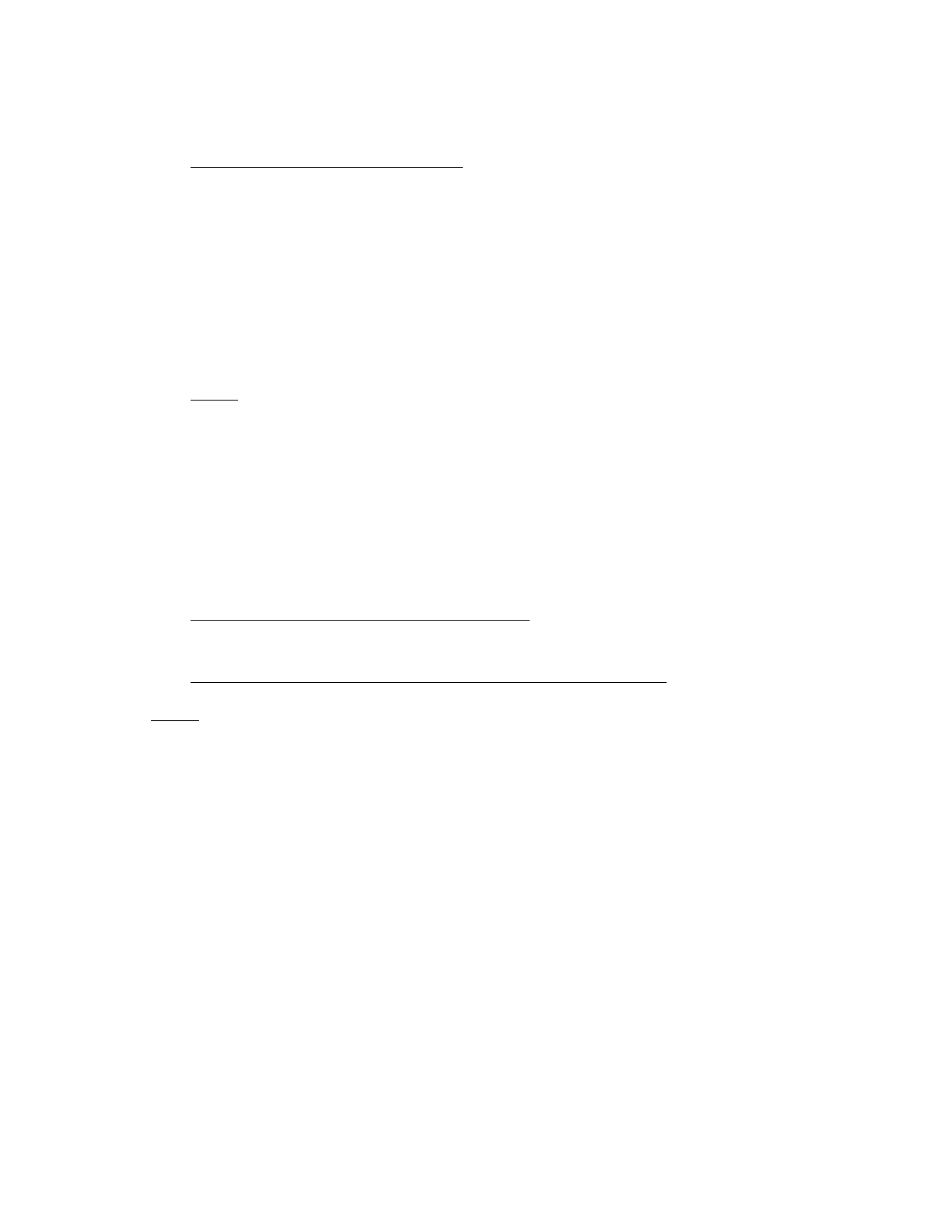
B. Aircraft Interface PWA (AI) Installation
(See Figure 701 or IPL Figure 1, Item 105)
AIRCRAFT INTERFACE PWA INSTALLATION PROCEDURE
NOTE: Apply Loctite to all screw installations for the following proced-
ures:
(1) Place the AI PWA (1−25) into position on the Rear Cover (1−10).
(2) Install the six screws (1−30) used to secure the AI PWA (1−25) to the rear cov-
er (1−10). Tighten screws to a torque value of 9−10 in./lbs.
(3) install the four screws (1−35) used to secure the Rear Connector J−1 to the
back of the rear cover (1−10). Tighten screws to a torque value of 5-6 in./lbs.
(4) Install the rear cover as described in Paragraph D, Rear Cover Installation.
The document reference is online, please check the correspondence between the online documentation and the printed version.
 Loading...