COMPONENT MAINTENANCE MANUAL
AVIATION PRODUCTS
Model FA5000
Rev. 02 Page 38
July 21/17
Description and Operation
23–70−30
Use or disclosure of information on this sheet is subject to
the restrictions on the cover page of this document.
7. THEORY OF OPERATION
The theory of operation provided for the Model FA5000 CVR describes the function of the
recorder both at the system level, PWA level and software operational level. System level
theory of operation describes the general operation of the system as a whole. Refer to
the Model FA5000 CVR System Block Diagram during the following discussion. The the-
ory of operation for each PWA describes the electrical circuitry of the major functional
groupings contained on the individual PWAs. The software level theory describes the
modes of operation of the recorder software.
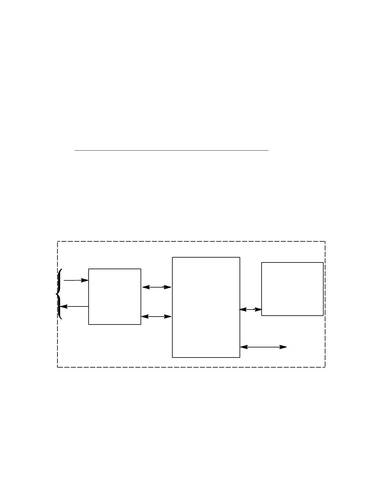
A. MODEL FA5000 CVR SYSTEM THEORY OF OPERATION
The ARINC 757/A, Model FA5000 CVR consists of three subassemblies, the Aircraft
Interface Printed Wiring Assembly (PWA), the CPU/Main Processor PWA, and Crash
Survivable Memory Unit (CSMU). The recorder interfaces with the aircraft’s cockpit
recorder control unit and microphone through the rear panel connector J1 and with
the Ground Station Equipment through the front panel Ethernet connector J2. The
descriptions and block diagrams of these subassemblies are provided in this section
to support level two maintenance coverage of this unit.
Aircraft
Interface
(AI)
J1
CPU/Main
Processor
Crash Surviv-
able
Memory Unit
Processor
(CSMU)
GSE –> PI/2
ETHERNET
Rear Front
HSS
– Digitized Audio Storage
– CVR Control
– Fault Processing
– Logic Power Supply
– ADPCM Encoding
– GMT Merging
– Signal Conditioning
– Power Supply
Aircraft
Signals &
Power
Analog
Audio
Signals
Power
Signals
Figure 20.
FA5000 CVR Overall Function Block Diagram
The document reference is online, please check the correspondence between the online documentation and the printed version.

 Loading...