COMPONENT MAINTENANCE MANUAL
AVIATION PRODUCTS
Model FA5000
Assembly
23–70–30
Use or disclosure of information on this sheet is subject to
the restrictions on the cover page of this document.
Rev. 02 Page 703
July 21/17
(1−25)
(1−30)
(Qty. 6)
(Qty. 4)
(1−35)
Rear Connector
J−1
Some parts are removed
for clarity purposes
NOTE:
Torque (9−10 in/lbs)
Torque (5−6
in/lbs)
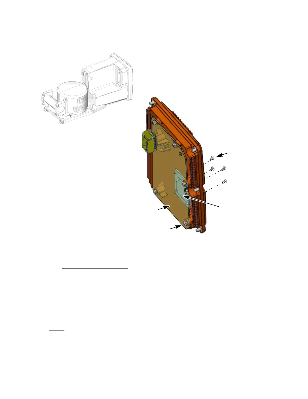
Figure 701.
Aircraft Interface PWA Installation Diagram
C. Rear Cover Installation
(See 703 or IPL Figure 1, Item 10)
REAR COVER INSTALLATION PROCEDURE
(1) Align the guide on the AI PWA (1−25) attached to the Rear Cover (1−10) with
the receptacle on the MP PWA (1−45).
(2) Slide rear cover (1−10) straight in the rear part of Shielded Housing (1−5) until
the AI PWA (1−25) and MP PWA (1−45) connectors are fully seated.
NOTE
: Apply Loctite to all screw installations for the following proced-
ures:
(3) Install four captive screws (1−15) used to secure the rear cover (1−10) to the
rear part of the Shielded Housing (1−5). Install two screws used to secure the
The document reference is online, please check the correspondence between the online documentation and the printed version.

 Loading...