Stow the lift truck
- Fix the chocks to the platform at the
front and at the back of each tyre
(Fig. H4/1) e (Fig. H4/3).
- Stow the lift truck on the platform with
enough resisting ropes. At the front of
the lift truck, on the fastening points 1
and 2 (Fig. H4/4).
- Tighten the ropes (Fig. H4/4).
H
H
5
5
-
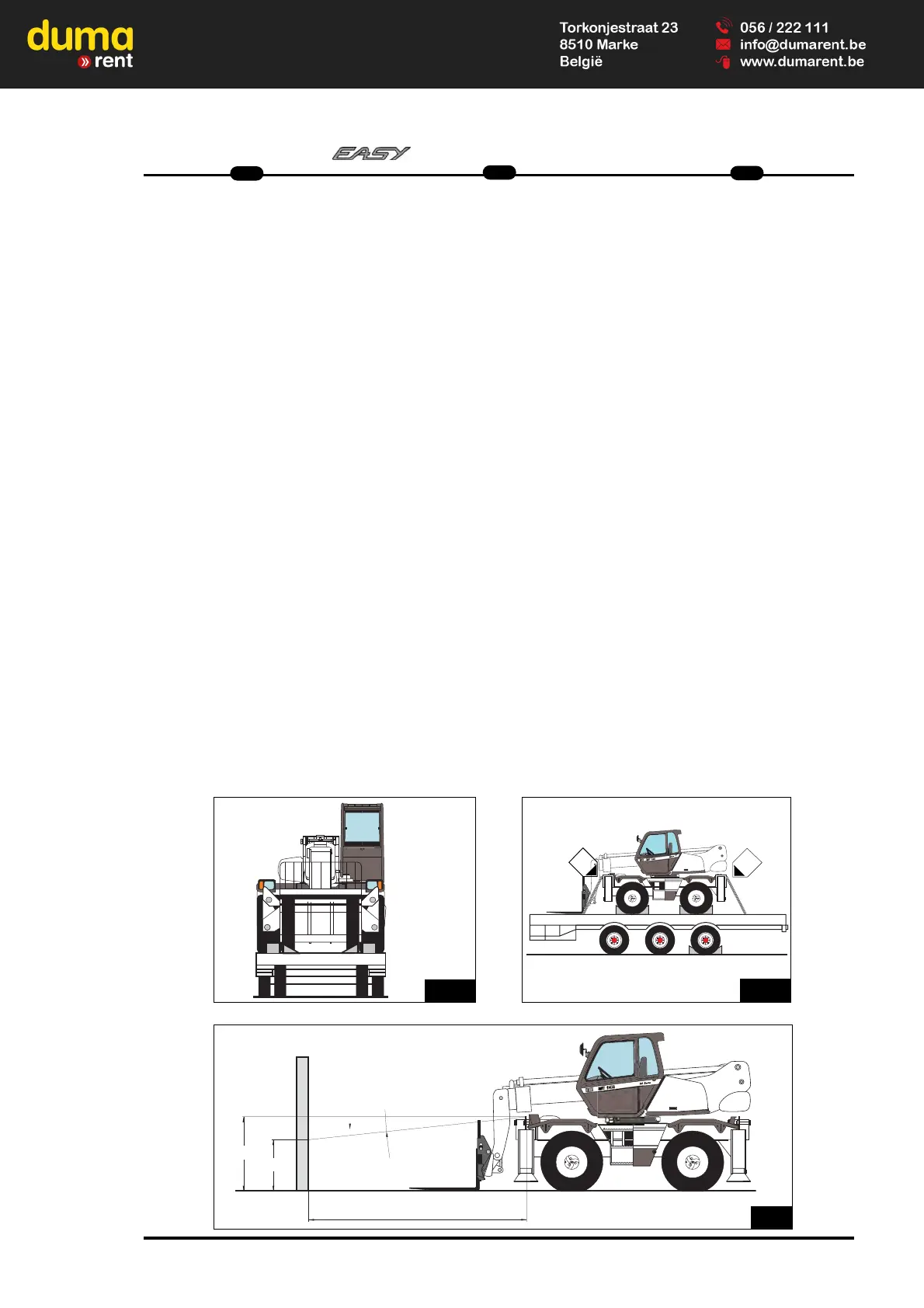
- Adjust the front headlamps
Recommended setting
(As per standard ECE-76/756 76/761 ECE20)
Set to - 2% of the dipped beam in rela-
tion to the horizontal line of the head-
lamp.
Adjusting procedure
- Place the lift truck unloaded and in the
transport position and perpendicular to
a white wall on flat, level ground (Fig.
H5).
- Check the tyre pressures (See
chapter : B3 - CHECK THE TYRE
PRESSURES AND THE WHEEL
NUTS TORQUE in paragraph : 3 -
MAINTENANCE).
- Put the gear reverser lever in neutral
and action the parking brake.
Calculating the height of the dipped
beam (h2) FIG. H5
h1 = Height of the dipped beam in
relation to the ground.
h2 = Height of the adjusted beam.
l = Distance between the dipped
beam and the white wall.
h2 = h1- (l x 2/100)
Teleskoplader befestigen
- Die Keile vor und hinter jedem Reifen
auf dem Sattelauflieger befestigen
(Abb. H4/1).
- Ebenfalls auf der Innenseite jedes
ReifensKeile auf dem Sattelauflieger
befestigen (Abb. H4/3).
- Den Teleskoplader mit geigneten
Gurten auf dem Sattelauflieger
verzurren.
Anschlagpunkten 1 und 2 (Abb. H4/2-
H4/3-H4/4).benutzen,
- Gurte spannen (Abb. H4/4).
H
H
5
5
-
- Scheinwerfer einstellen
Einstellungshinweise
(Nach Norm ECE-76/756 76/761
ECE20)
Justieren des Abblendlichtstrahls um -
2% zur waagerechten
Scheinwerferachse.
Einstellungsverfahren
- Den Teleskoplader leer und in
Transportposition auf einer ebenen
Fläche im rechten Winkel zu einer
weißen Wand aufstellen (Abb.H5).
- Reifendruck prüfen (Siehe Kapitel :
B3 - REIFENDRUCK UND SITZ DER
RADMUTTERN ÜBERPRÜFEN,
Abschnitt :3 - WARTUNG).
- Fahrtrichtungswahlschalter in Neutral.
Handbremse lösen.
Höhenberechnung des Abblendlicht
(h2) ABB. H5
h1 = Höhe des Abblendlichts zum Boden.
h2 = Höhe des eingestellten Lichtstrahls.
I = Abstand zwischen dem Abblendlicht
und der weißen Wand.
h2 = h1- (l x 2/100)
Imbarcare un carrello elevatore
- Fissare i cunei davanti e dietro a
ciascun pneumatico (Fig. H4/1) e
(H4/3).
- Bloccare il carrello elevatore sulla
piattaforma con funi sufficientemente
resistenti, sulla parte anteriore del
carrello elevatore nei punti di
ancoraggio 1 e 2 (Fig. H4/4).
- Portare le funi in tensione (Fig. H4/4).
H
H
5
5
-
- Regolare i fari anteriori
Raccomandazioni per la regolazione
( Secondo le norme ECE-76/756 76/761
ECE20).
Regolazione del -2% del fascio degli
anabbaglianti rispetto all’asse orizzonta-
le del proiettore.
Procedura di regolazione
- Mettere il carrello elevatore, a vuoto in
posizione di trasporto,
perpendicolarmente ad un muro
bianco, su di un terreno piano e
orizzontale (Fig. H5).
- Controllare la pressione dei pneumatici
(Vedi capitolo: B3 - CONTROLLARE
LA PRESSIONE DEI PNEUMATICI E
IL SERRAGGIO DEI BULLONI DELLE
RUOTE nella parte: 3 - MANUTENZIONE).
- Mettere la leva dell’invertitore di marcia
in folle e azionare il freno di
stazionameto.
Calcolo dell’altezza degli
anabbaglianti (h2) FIG. H5
h1 = Altezza rispetto al suolo degli
anabbaglianti.
h2 = Altezza del fascio regolato.
I = Distanza tra gli anabbaglianti e il
muro bianco.
h2 = h1- (l x 2/100)
 Loading...