HYDRAULIC SYSTEM 14000 SERVICE MANUAL
2-26
Published 09-05-14, Control # 226-02
High Pressure Adjustment
The following adjustment is only required when a system
fails the High Pressure Test described in this section.
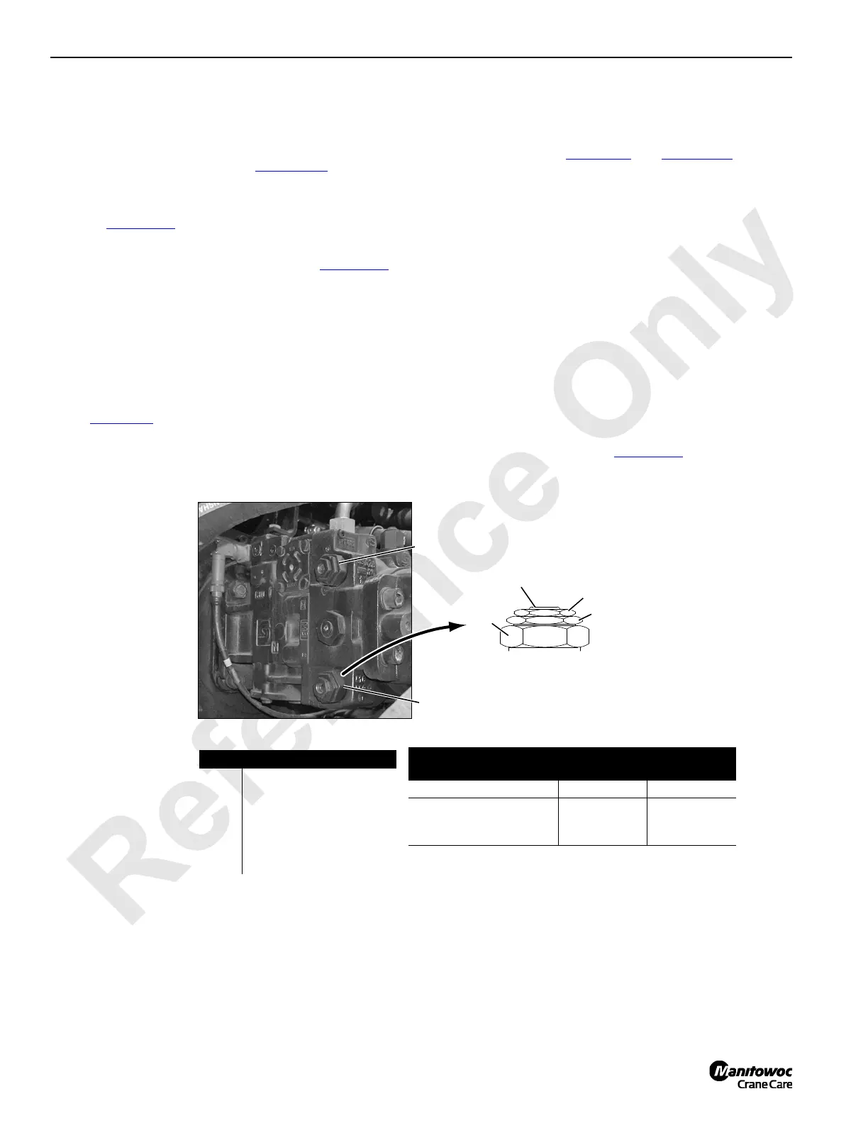
Unless otherwise specified, see Figure 2-25
for following
procedure.
1. Scroll to diagnostic screen for corresponding function
(see Figure 2-15
).
2. Disconnect electrical (DIN) connector from
corresponding brake solenoid valve (see Figure 2-13
).
3. With engine running at low idle, slowly move desired
control handle:
• In either direction from off for swing or travel.
• Back from off (hoist direction) for all drums.
4. Do not demand any more than 20% handle command.
5. Pressure on screen should indicate pressure specified
in Table 2-10
.
6. If proper pressure is not indicated, adjust corresponding
multi-function valve:
a. Remove protective cap (3) from multi-function valve
(1 or 2). See Table 2-10
and Figure 2-19 for pump
port identification.
b. Loosen lock nut (4).
DO NOT tamper with bypass hex (6). See pump
manufacturer’s instructions.
c. Using an internal hex wrench, adjust multi-function
valve adjusting screw (5).
- Turn IN to INCREASE pressure.
- Turn OUT to DECREASE pressure.
7. Repeat steps until specified pressure is indicated.
8. Hold adjusting screw (5) in position and securely tighten
lock nut (4).
9. Install protective cap (3).
10. Reconnect electrical (DIN) connector to corresponding
brake solenoid valve (see Figure 2-13
).
P1537a
Item Description
1 Port A Multi-Function Valve
2 Port B Multi-Function Valve
3Protective Cap
4 Lock Nut
5 Adjusting Screw
6Bypass Hex
Wrench Size
Pump Size
Lock Nut
Hex Size
Internal
Hex Size
Series 042 -100 Units 19 mm 5 mm
Series 130 Units
13 mm
or
24 mm
4 mm
or
8 mm
Multi-Function Valve
A1161
FIGURE 2-25
1
4
6
1
3 (5 under)
2
2
Typical Pump Installation

 Loading...


