INTRODUCTION 14000 SERVICE MANUAL
1-50
Published 09-05-14, Control # 226-02
UPPER ACCESSORY SYSTEM
Upper accessory system components includes gantry
cylinders, mast raising cylinders, boom hinge pin cylinder,
and cab tilt cylinder. Lower accessory system components
includes crawler pins and four carbody jacks.
When a high pressure accessory system component is
enabled, an input signal is sent to node 1 controller. Node 1
controller sends a variable 0 to 24 volt signal to low-pressure
side of drum 1 pump EDC. Drum 1 pump provides system
pressure of up to 4,000 psi (275 bar) depending on system
enabled.
Gantry System
See Figures 1-28, 1-29, and 1-30.
Each gantry cylinder has a counterbalance valve at each
cylinder port. These valves ensure smooth control when
raising or lowering gantry and locks cylinder in place when
gantry is at a desired position or if a hydraulic line fails.
Gantry accessory valve is motor spool where both cylinder
ports and tank port of valve spool section are connected in
center position. This prevents premature opening of load
equalizing valves. The accessory system pressure sender
monitors accessory system pressure.
Gantry raising and lowering is controlled by gantry cylinders
switch on setup remote control. Power is available to setup
remote control when cable is plugged into W36 receptacle
on node 3, remote control on is selected on remote control
function screen, and engine is running.
Select a liftcrane mast capacity chart when using gantry for
setup. Mast and gantry controls will not operate properly and
mast operating limits will remain off until proper capacity
chart is selected.
Remove existing W36 cable and plug setup remote cable
into receptacle. Pressing power button completes power
supply circuit to setup remote control switches.
A gantry down fault appears on Main display, Information
screen if gantry maximum limit switch circuit is not closed.
Raise gantry with gantry cylinders switch until gantry
maximum limit switch is closed.
Gantry Cylinders Raise
NOTE: Gantry back hitch pins must be disengaged before
raising or lowering gantry. See Back Hitch Pin
Cylinders topic in this section. The mast will raise
with gantry.
Move gantry cylinders toggle up and hold to raise gantry
(extend cylinders). An input voltage is sent to node 1
controller. Node 3 controller sends a 24 volt output to enable
gantry cylinders raise solenoid HS-24 and shifts valve to
raise position. Solenoid valve shifts to block tank port and
open port to low-pressure side of drum 1 pump. Node 4
controller sends a variable 0 to 24 volt output to enable low-
pressure side of drum 1 pump EDC.
Hydraulic fluid from low-pressure side of drum 1 pump flows
to gantry cylinder raise solenoid HS-24 of upper accessory
valve and through free-flow check valve sections on side A of
load equalizing valve. From equalizing valve, fluid enters
counterbalance valves and piston end of gantry cylinders,
extending cylinder rods to raise gantry.
Free-flow check valve sections on side B of counterbalance
valves block fluid exhausting from rod end of gantry
cylinders. Fluid passes through flow restrain sections of
counterbalance valve that have a relief setting of 3,500 psi
(240 bar). Counterbalance valves act as a deceleration
control and operate with a 5:1 pilot ratio of the relief valve
pressure, permitting the valves to open when pressure in the
piston end of cylinders is approximately 700 psi (48 bar).
Exhaust fluid from side B of both counterbalance valves
combines and fluid passes through non-restrictive part of
load equalizing valve before entering accessory system
valve. Hydraulic fluid exits through the gantry valve section
and returns to tank.
Free-flow check valve sections on side B of load equalizing
valve block the flow. Hydraulic fluid then passes through flow
restrain section of valve that is preset at 4,000 psi (275 bar).
Load equalizing valve operates with a 1.5:1 pilot ratio of the
relief valve pressure, permitting valve to open when fluid
pressure on side A of the valve is approximately 2680 psi
(185 bar). Restraining section on side B of load equalizing
valve opens, controlling fluid out of both cylinders and
ensuring cylinder actuation is balanced.
When gantry is fully raised the back hitch pins automatically
engage and gantry maximum limit switch closes sending an
input signal node 1 controller. Node 4 controller sends a zero
volt output signal to drum 1 pump EDC to de-stroke the
pump. Node 3 controller sends an output signal to shift
gantry cylinder raise solenoid HS-24 to center position. The
next step in sequence is raising mast (see Mast System topic
in this section).
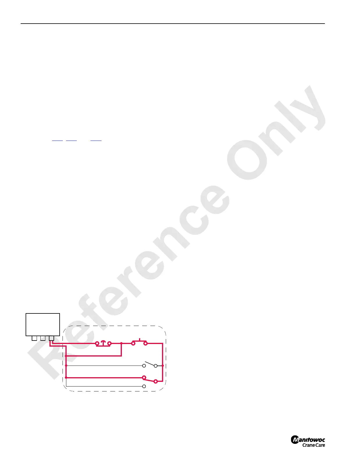
FIGURE 1-28
Cable
Setup Remote Control
W36
Node 3
Back Hitch Pins Disengage
Power
Emergency
Stop
Gantry Cylinders Raise
Gantry Cylinders Lower
14CSM1-118
24 Volts
AI-13
DI-7
AI-11
AI-12

 Loading...


