Manitowoc Published 09-05-14, Control # 226-02 3-11
14000 SERVICE MANUAL ELECTRIC SYSTEM
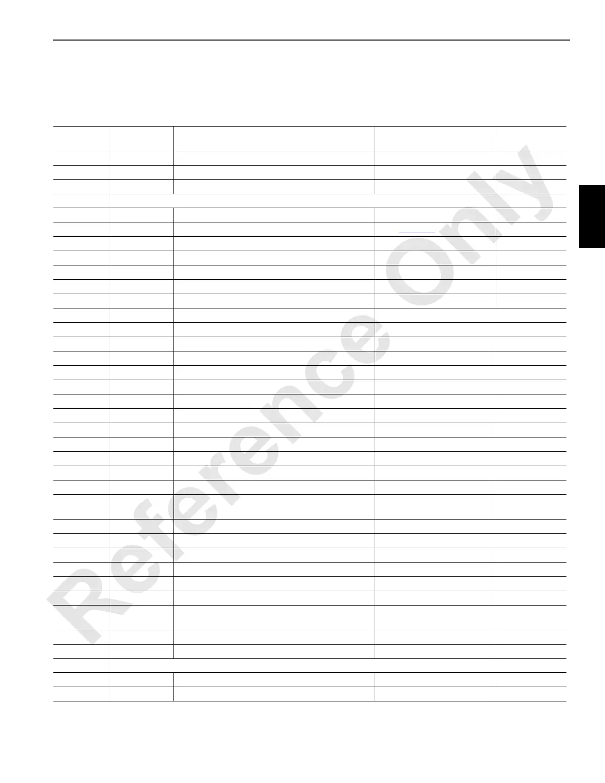
Node 3—Drum 1, 2 & 3, Alarms, Sensors, and
Accessories
See Electrical Schematic A17144, Sheets 8, 9, 17 and 18 (at end of this section).
Receptacle
Number
Function
Type
Description Test Voltages
CAN Packet
Number
J7-WN04
I/O Cable — From Node 5 to Node 3 N/A (option)
J7-WN08
I/O Cable — From Node 4 to Node 3 N/A
J1-WN10
I/O Cable — From Node 3 to Node 2 N/A
J3/W33 Receptacle — Drum 1, Gantry, Mast, Pressure Senders, Limits, and Angles
33-A Ground
Drum 1 Motor Control Ground
33-B DO-1
Drum 1 Motor Control See Table 3-2 for Values CAN21-1-1
33-C Ground
Drum 1 Brake/Gantry Cylinder - Retract Ground
33-D DO-2
Drum 1 Brake Release 0 Volts Off; 24 Volts On CAN21-1-2
33-E Ground
Drum 3 Minimum Bail Ground
33-F DO-3
Gantry Cylinder - Retract 0 Volts Off; 24 Volts On CAN21-1-4
33-G Ground
Gantry Cylinder - Extend/Mast Cylinder - Extend Ground
33-H DO-4
Gantry Cylinder - Extend 0 Volts Off; 24 Volts On CAN21-1-8
33-J Ground
Drum 1 Minimum Bail/Drum 2 Minimum Bail Ground
33-L NS-2
Node Select 2 Jumper to Ground 0 Volts (With Jumper)
33-N Ground
Mast Cylinder - Retract/Max. Boom Angle Limit Ground
33-P DO-6
Mast Cylinder - Retract 0 Volts Off; 24 Volts On CAN21-1-32
33-R DO-5
Mast Cylinder - Extend 0 Volts Off; 24 Volts On CAN21-1-16
33-V 24 Volts
Drum 3 Minimum Bail 24 Volts Nominal
33-X 24 Volts
Drum 1 Minimum Bail/Drum 2 Minimum Bail 24 Volts Nominal
33-Z 24 Volts
Accessory System Pressure Sender 24 Volts Nominal
33-b AI-2
Drum 1 Minimum Bail 0 Volts Off; 24 Volts On CAN4-2-32
33-c AI-3
Drum 3 Minimum Bail 0 Volts Off; 24 Volts On CAN4-2-64
33-e AI-5
Maximum Boom Angle Limit 0 Volts Off; 24 Volts On CAN5-2-16
33-d AI-4
Drum 2 Minimum Bail 0 Volts Off; 24 Volts On CAN4-2-128
33-f AI-6
Accessory System Pressure Sender
1 Volt at 0 psi,
5 Volts at 7,000 psi
CAN5-2-32
33-g Ground
Jumper to Node Select 2 Ground
33-h Ground
Accessory System Pressure Sender Ground
33-j 5 Volts
Mast Angle Sensor 5 Volts Nominal
33-k Ground
Drum 1 Pressure Sender Ground
33-m Ground
Mast Angle Sensor Ground
33-n 24 Volts
Drum 1 Pressure Sender 24 Volts Nominal
33-p AI-7
Drum 1 Pressure Sender
1 Volt at 0 psi,
5 Volts at 7,000 psi
CAN5-2-64
33-r AI-8
Mast Angle Sensor Variable 0 to 5 Volts CAN5-2-128
33-s
24 Volts
Maximum Boom Angle Limit 24 Volts Nominal
J4/W34 Receptacle - Drum 3, Travel Brakes, Swing Brakes, Pawls, Cab Tilt, and Back Hitch Pins
34-A Ground
Travel Brake Release Ground
34-B DO-11
Travel Brake Release 0 Volts Off; 24 Volts On CAN21-2-4

 Loading...


