HYDRAULIC SYSTEM 14000 SERVICE MANUAL
2-28
Published 09-05-14, Control # 226-02
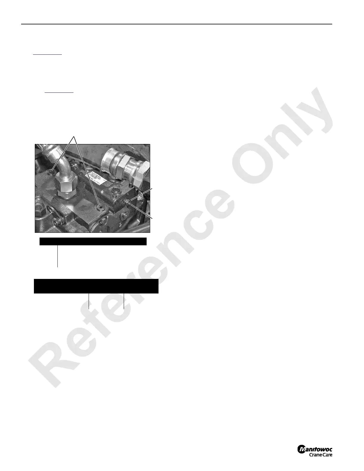
Pump Neutral Adjustment
See Figure 2-27 for following procedure.
To adjust pump neutral:
1. Park all crane functions and stop engine.
2. Disconnect electrical (DIN) connector from pump EDC
(see Figure 2-29
).
3. Install an accurate 0 to 1,000 psi (0 to 69 bar) hydraulic
pressure gauge in each servo gauge port (1).
4. Start and run engine at high idle.
5. Loosen lock nut (2).
6. Using an internal hex wrench, turn adjusting screw (3) in
until pressure increases in either gauge.
7. Note angular position of internal hex wrench.
8. Then, turn adjusting screw out until pressure increases
an equal amount in other gauge.
9. Again, note angular position of internal hex wrench.
10. Turn adjusting screw in half the distance between
positions noted above.
11. Pump control should now be in neutral with both gauges
reading same pressure.
12. Hold adjusting screw (3) in position and securely tighten
lock nut (2).
13. Stop engine, remove gauges, and securely install servo
gauge port plugs (1).
1
2
Item Description
1 Servo Gauge Ports (SAE 06)
2 Lock Nut
3 Adjusting Screw
Wrench Size
Pump Series
Lock Nut
Hex Size
Internal
Hex Size
Early Series Units 17 mm 5 mm
Current Series Units 10 mm 3 mm
FIGURE 2-27
P1535a
Typical Pump Installation
3

 Loading...


