EasyManuals Logo
Home>Manitowoc>Construction Equipment>14000

Manitowoc 14000 Service Maintenance Manual

Manitowoc 14000
278 pages
To Next Page IconTo Next Page
To Previous Page IconTo Previous Page
Page #153 background imageLoading...
Page #153 background image
Reference Only
Manitowoc Published 09-05-14, Control # 226-02 3-31
14000 SERVICE MANUAL ELECTRIC SYSTEM
3
Accessory Diagnostic Screen
Select mast cylinders and boom pin icons in screen level 1
as shown in Figure 3-16
. Press Enter button to go to level 2.
In level 2, there are two diagnostic screens.
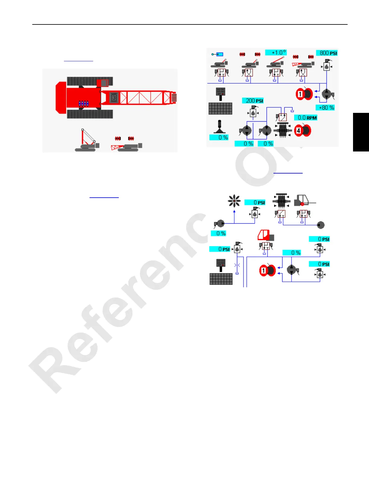
In diagnostic screen one, gantry cylinders up/down with up
limit switch, back hitch pins, mast arm cylinders and boom
hinge pins are shown (Figure 3-17
).
In diagnostic screen two, rigging winch, cab tilt and the
cooling fan system are shown (Figure 3-18
).
FIGURE 3-16
14COM3-39
FIGURE 3-17
14COM3-40
Mast Selected
FIGURE 3-18
MAINSCREEN 4V

Table of Contents

Other manuals for Manitowoc 14000

Questions and Answers:

Question and Answer IconNeed help?

Do you have a question about the Manitowoc 14000 and is the answer not in the manual?

Manitowoc 14000 Specifications

General IconGeneral
BrandManitowoc
Model14000
CategoryConstruction Equipment
LanguageEnglish

Related product manuals