Published 4-20-2015, Control # 502-01 4-21
RT540E SERVICE MANUAL BOOM
3. Insert the upper wear pad, backing plate and adjusting
plate. (Figure 4-47, 3)
a. Attach each wear pad assembly with four washers,
four lock washers and four capscrews.
b. Insert the hex head adjusting screws. Do not
tightened at this time
4. Apply lubricant to the wear pad contact areas of the Fly
Section.
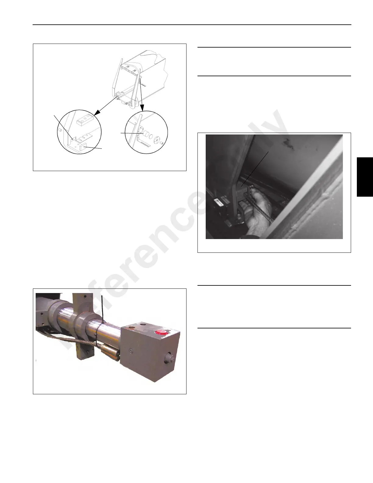
5. To aid in the installation of the Fly Section into the Outer
Mid Section, apply lubricant to the wear pad contact
areas of the Fly Section and secure the Extend Cables
to the Tele Cylinder. (Figure 4-48)
a. Rotate the Port Block as shown in Figure 4-48.
6. Attach the fly retract cables to the cable anchors
(Figure 4-49, 1) on the base end of the fly section on
both sides. Install the two cable keepers with two lock
washers and two bolts on each keeper.
7. Feed the threaded end through outer mid and lay out
towards the front of the outer mid section.
8. Slide the Fly section into the Outer Mid section until the
wear pad adjustment is accessible though the access
plate on top of the Outer Mid section.
9. Raise the Fly Section slightly and insert the bottom wear
pad in to place and secure with retaining bolts. Insert the
bolts (Figure 4-50, 1) from the bottom of the Outer Mid
Section.
CAUTION
Do not allow the cables to become entangled or overlap.
cable or boom failure could result.
CAUTION
Pull the two fly retract cables through the outer mid as the
fly section is being installed. Do not allow the cables to
become entangled or overlap. Cable or boom failure could
result.
Reference Only

 Loading...


