Published 4-20-2015, Control # 502-01 4-25
RT540E SERVICE MANUAL BOOM
7. Assemble the Fly retract sheave assembly as shown in
Figure 4-63 and Figure 4-64. Note that the pin has one
thrust washer to the inside of the boom and two thrust
washers to the outside of the boom.
8. Lubricate both sheave assemblies
9. Install the rear bottom and side and brass wear pads.
Install shims with the open end facing the base end of
the boom section.
10. Install adjustment bolts and lock nuts to the upper
adjustable wear pad weldment. Do not install wear pads
at this time (Figure 4-65).
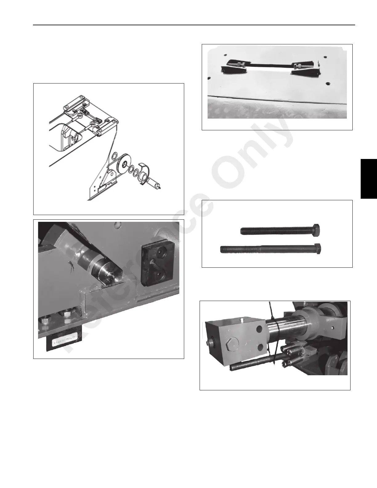
NOTE: Installation of the Extend Cable Anchor Assembly
will require the use of a bolt longer than the
permanent bolt. The weight of the five extend
cables and anchor assembly will make the
installation of the anchor assembly extremely
difficult with out use of a longer bolt Figure 4-66.
Use bolt Part Number 7099000555 (or equivalent)
for installation only (Figure 4-66).
.
11. Insert assembly bolt into extend cable anchor.
12. Tie the extend cable anchor assembly to the Tele
Cylinder (Figure 4-67).
13. Assemble the Fly Retract Cable anchor weldments to
the retract cables. Thread the single nut on the cable
end until there is 1 1/2 inch of thread showing, then
install the locknut (Figure 4-68)
.
NOTE: There are left and right anchors. Check to make
sure the anchors are in the correct position
FIGURE 4-66
Permanent Anchor Bolt
Assembly Bolt
Reference Only

 Loading...


